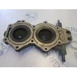
0398752 CYL,AY TILT EVINRUDE
E40ECEC, E40EESR, E48ESLCER, E48ESLCER, E50BECEC, E50BEESR, E50TELCEC, VE48ESLCER
CYL

Price: query
Rating:
Number on catalog scheme: 39875

BRP EVINRUDE entire parts catalog list:
- STERN AND SWIVEL BRACKET » 0398752
E48ESLCER 1989
E48ESLCER 1989
E50BECEC, E50BELCEC, E50TLCEC, TE50TLCEC, TE50TLESF 1989
E50BEESR, E50BELESR, E50TELESR, E50TLESR, TE50TLESF, TE50TLESR, VE50BEESR, VE50BELESR, VE50TLESR 1990
E50TELCEC 1989
VE48ESLCER 1989
Information:
Table 1
J1939 and Description Comments
100-3
Engine Oil Pressure : Voltage Above Normal The Electronic Control Module (ECM) detects signal voltage that is not in the acceptable range.
The value of the parameter is set to a default value.
The code is logged.
100-4
Engine Oil Pressure : Voltage Below Normal The Electronic Control Module (ECM) detects signal voltage that is not in the acceptable range.
The value of the parameter is set to a default value.
The code is logged.
108-3
Barometric Pressure : Voltage Above Normal The Electronic Control Module (ECM) detects signal voltage that is not in the acceptable range.
The value of the parameter is set to a default value.
The code is logged.
108-4
Barometric Pressure : Voltage Below Normal The Electronic Control Module (ECM) detects signal voltage that is not in the acceptable range.
The value of the parameter is set to a default value.
The code is logged.
109-3
Engine Coolant Pressure : Voltage Above Normal The Electronic Control Module (ECM) detects signal voltage that is not in the acceptable range.
The value of the parameter is set to a default value.
The code is logged.
109-4
Engine Coolant Pressure : Voltage Below Normal The Electronic Control Module (ECM) detects signal voltage that is not in the acceptable range.
The value of the parameter is set to a default value.
The code is logged.
1208-3
Engine Pre-filter Oil Pressure : Voltage Above Normal The Electronic Control Module (ECM) detects signal voltage that is not in the acceptable range.
The value of the parameter is set to a default value.
The code is logged.
1208-4
Engine Pre-filter Oil Pressure : Voltage Below Normal The Electronic Control Module (ECM) detects signal voltage that is not in the acceptable range.
The value of the parameter is set to a default value.
The code is logged.
4817-3
Engine Intake Manifold #1 Absolute Pressure : Voltage Above Normal The Electronic Control Module (ECM) detects signal voltage that is not in the acceptable range.
The value of the parameter is set to a default value.
The code is logged.
4817-4
Engine Intake Manifold #1 Absolute Pressure : Voltage Below Normal The Electronic Control Module (ECM) detects signal voltage that is not in the acceptable range.
The value of the parameter is set to a default value.
The code is logged.
5631-3
Engine Throttle Valve Differential Pressure : Voltage Above Normal The Electronic Control Module (ECM) detects signal voltage that is not in the acceptable range.
The value of the parameter is set to a default value.
The code is logged.
5631-4
Engine Throttle Valve Differential Pressure : Voltage Below Normal The Electronic Control Module (ECM) detects signal voltage that is not in the acceptable range.
The value of the parameter is set to a default value.
The code is logged. The Electronic Control Module (ECM) continuously creates a pull-up voltage on the signal wire for each sensor. The ECM uses this pull-up voltage to detect a problem in the signal circuit. When the ECM detects voltage that is above a threshold on the signal wire, the ECM activates a high voltage -3 diagnostic . When the ECM detects voltage that is below a threshold on the signal wire, the ECM activates a low voltage -4 diagnostic .Note: There may be a delay of 30 seconds for Cat® Electronic Technician (Cat ET) Service Tool to display an active diagnostic . When you check for a diagnostic , be sure to wait at least 30 seconds.
Illustration 1 g06493672
For the complete circuit details, refer to the full schematic.
Table 2
Troubleshooting Test Steps Values Results
1. Check for Codes
A. Connect the Cat® Electronic Technician (Cat ET) Service Tool to the service tool connector.
B. Determine if a code is active or logged.
Codes
Result: A -3 code is active.
Proceed to Test Step 2.
Result: A -4 code is active.
Proceed to Test Step 3.
2. Create a Short at the Sensor Connector
A. Turn the keyswitch to the OFF position.
B. Disconnect the sensor with the active -3 code.
C. Install the jumper wire between the following terminals at the sensor connector:
- Terminal 3 (signal) and Terminal 2 (sensor return)
D. Connect Cat ET.
E. Use Cat ET to monitor the following:
- -4 code
F. Turn the keyswitch to the OFF position.
Create a Short
Result: A -4 code did not become active.
Proceed to Test Step 4.
Result: A -4 code became active.
Repair: The wiring harness is OK. Replace the sensor.
Verify that the repair eliminated the problem.
3. Create an Open at the Sensor Connector
A. Turn the keyswitch to the OFF position.
B. Disconnect the sensor with the active -4 code.
C. Connect Cat ET.
D. Use Cat ET to monitor the following:
- -3 code
E. Turn the keyswitch to the OFF position.
Create an Open
Result: A -3 code did not become active.
Proceed to Test Step 4.
Result: A -3 code became active.
Repair: The wiring harness is OK. Replace the sensor.
Verify that the repair eliminated the problem.
4. Check the 5 VDC Supply Voltage at the Sensor Connector
A. Turn the keyswitch to the ON position.
B. Measure the voltage at the sensor connector between the following pins:
- Pin 1 and Pin 2
C. Reconnect the sensor.
5.0 0.2 VDC
Result: The supply voltage is 5.0 0.2 VDC.
Proceed to Test Step 5.
Result: The supply voltage is not 5.0 0.2 VDC.
Repair:Repair or replace the wiring harness.
If the problem is not resolved, proceed to Test Step 5.
5. Perform the Wiggle Test
Carefully following this procedure is the best way to identify the root cause of an intermittent problem.
A. Connect Cat ET.
B. Use CAT ET to perform the following test:
- "Wiggle Test"
C. Slowly wiggle the wiring and the connectors between the Electronic Control Module (ECM) connector and the sensor. Pay particular attention to the wiring near each connector. Be sure to wiggle all the wiring.
As you wiggle the wiring look for these problems:
- Loose connectors or damaged connectors
- Moisture on the connectors or the wiring
- Damaged that is caused by excessive heat
- Damage that is caused by chafing
- Improper routing of wiring
- Damaged insulation
Test
Result: The wiring failed the Wiggle Test.
Repair: There is a problem with the wiring harness. Repair or replace the wiring harness.
Verify that the repair eliminated the problem.
Result: The wiring passed the Wiggle Test.
Repair: The problem may be intermittent. Inspect the wiring harness. Refer to Troubleshooting, "Electrical Connectors - Inspect" for additional information.
If the wiring looks OK, perform the
Parts cyl EVINRUDE:
0397517
0397517 CYL,CRKC,DWL AY
E40ECEC, E40EEIA, E40EENJ, E40EESR, E48ESLCER, E48ESLCER, E48ESLEIM, E48ESLEIM, E48ESLENB, E48ESLENB, E48ESLESA, E48ESLESA, E50BECEC, E50BEEIA, E50BEENJ, E50BEESR, E50TELCEC, VE48ESLCER, VE48ESLENB
0398872
0398872 CYL,CRKC,DWL AY
E40ECEC, E40EEIA, E40EENJ, E40EESR, E50BECEC, E50BEEIA, E50BEENJ, E50BEESR, E50TELCEC
0432618
0432618 CYL HEAD AY
E40ECEC, E40EEIA, E40EENJ, E40EERE, E40EESR, E40EETB, E50BECEC, E50BEEIA, E50BEENJ, E50BEERE, E50BEESR, E50BEETB, E50TELCEC
0432619
0432619 CYL HEAD AY
E40ECEC, E40EEIA, E40EENJ, E40EERE, E40EESR, E40EETB, E48ESLCER, E48ESLCER, E48ESLEIM, E48ESLEIM, E48ESLENB, E48ESLENB, E48ESLERD, E48ESLERD, E48ESLESA, E48ESLESA, E48ESLETE, E48ESLETE, E50BECEC, E50BEEIA, E50BEENJ, E50BEERE, E50BEESR, E50BEETB, E50T