14620-PNA-040 ARM ASSY., ROCKER Honda
BF150A4 LA, BF150A4 XA, BF150A4 XCA, BF150A5 LA, BF150A5 XA, BF150A5 XCA, BF150A6 LA, BF150A6 XA, BF150A6 XCA, BF150AK0 LA, BF150AK0 XA, BF150AK0 XCA, BF150AK2 LA, BF150AK2 XA, BF150AK2 XCA
ARM

Price: query
Rating:
You can buy parts:
As an associate, we earn commssions on qualifying purchases through the links below

Genuine OEM for Honda Rocker Arms Civic Type R FN2 07-11 K20Z 14620PNA040 14620-PNA-040
Generic This is a genuine Japanese part || for Honda Rocker Arms Civic Type R FN2 07-11 K20Z || Part number: 14620-PNA-040 || Please verify the compatibility before making a purchase || To ensure fitment, match the part number or provide us your VIN
Generic This is a genuine Japanese part || for Honda Rocker Arms Civic Type R FN2 07-11 K20Z || Part number: 14620-PNA-040 || Please verify the compatibility before making a purchase || To ensure fitment, match the part number or provide us your VIN
$250.33
24-09-2017
Acura: Acura
Acura 14620-PNA-040, Engine Rocker Arm
Genuine Acura OEM product
Genuine Acura OEM product

$201.28
02-09-2024
14.0[6.30] Pounds
JP: ARIGATOU STORE
Genuine Honda (14620-PNA-040) Rocker Arm Assembly
Honda Civic 4D '09 || Genuine OEM || Direct fit || Genuine Honda Parts 14620-PNA-040 Rocker Arm Assembly
Honda Civic 4D '09 || Genuine OEM || Direct fit || Genuine Honda Parts 14620-PNA-040 Rocker Arm Assembly
Number on catalog scheme: 14

Compatible models:
Honda entire parts catalog list:
- CAMSHAFT VALVE » 14620-PNA-040
- CAMSHAFT VALVE » 14620-PNA-040
- CAMSHAFT VALVE » 14620-PNA-040
- CAMSHAFT VALVE » 14620-PNA-040
- CAMSHAFT VALVE » 14620-PNA-040
- CAMSHAFT VALVE » 14620-PNA-040
- CAMSHAFT VALVE » 14620-PNA-040
- CAMSHAFT VALVE » 14620-PNA-040
- CAMSHAFT VALVE » 14620-PNA-040
- CAMSHAFT VALVE » 14620-PNA-040
- CAMSHAFT VALVE » 14620-PNA-040
- CAMSHAFT VALVE » 14620-PNA-040
- CAMSHAFT VALVE » 14620-PNA-040
- CAMSHAFT VALVE » 14620-PNA-040
- CAMSHAFT VALVE » 14620-PNA-040
Information:
Start By:a. remove fan assembly
At operating temperature, the engine coolant is hot and under pressure. Steam can cause personal injury. Drain the coolant only after the engine has been stopped and the fill cap is cool enough to touch with your bare hand. Remove the fill cap from the radiator slowly to relieve pressure. Cooling system conditioner contains alkali. Avoid contact with the skin and eyes to prevent personal injury.
1. Drain the coolant from the radiator. The capacity of the cooling system is 30 liters (7.8 U.S. Gal).
At operating temperature, the hydraulic oil tank is hot and under pressure. Hot oil can cause severe burns. Remove the drain plug only when the engine is stopped, and the drain plug is cool enough to touch with your bare hand.
2. Drain the hydraulic oil tank. The capacity of the hydraulic oil tank is 125 liters (32.5 U.S. Gal).3. Remove the hood assembly.
View from underneath the radiator.4. Disconnect two lines (1). 5. Disconnect the upper and lower radiator hoses (2).6. Remove three bolts and washers (3) from each side of radiator and hydraulic oil cooler (4). 7. Disconnect one hydraulic oil line (5). 8. Install Tooling (A), and support the radiator and hydraulic oil cooler (4) with chains and a hoist as shown. Remove radiator and hydraulic oil cooler (4). The weight of the radiator and hydraulic oil cooler is 57 kg (125 lb). The following steps are for the installation of the radiator and hydraulic oil cooler.9. Position radiator and hydraulic oil cooler (4) in the frame.10. Install three bolts and washers (3) to each side, and secure radiator and hydraulic oil cooler (4). Remove Tooling (A) from the radiator.11. Connect one hydraulic oil line (5) and two additional lines (1).12. Connect upper and lower radiator hoses (2).13. Install the hood.14. Fill the radiator with coolant. See the topic "Lubricant Viscosities & Refill Capacities" in the Operation & Maintenance Manual for the correct procedures.15. Fill the hydraulic oil tank. See the topic "Lubricant Viscosities & Refill Capacities" in the Operation & Maintenance Manual for the correct procedures.End By:a. install fan assembly Some excavators may be equipped with an optional hydraulic oil cooler fan. For information regarding the removal and installation, refer to Vehicle Systems module, form no. SENR4346.Separate & Connect Radiator & Hydraulic Oil Cooler
Start By:a. remove radiator and hydraulic oil cooler 1. Disconnect two lines (1) from reservoir tank group (2).2. Remove three bolts and washers (3), and remove reservoir tank group (2). 3. Remove six bolts and washers (4), three from each side, and remove shroud (5). By removing two bolts and washers (6) and two bolts and washers (8), the radiator and the oil cooler can be removed at the same time, and then separated. To complete the separation, remove the remaining two bolts and washers (6). 4. Remove four bolts and washers (6), and remove radiator (7).5. Remove two bolts and washers (8), and remove hydraulic oil cooler (9). 6. Remove thermostat valve group (10) from hydraulic oil cooler (9). The following steps are for the connecting of the radiator and the oil cooler.7. Install thermostat valve group (10) into hydraulic oil cooler (9).8. Position hydraulic oil cooler (9), and secure into place with two bolts and washers (8).9. Position the radiator (7), and secure by installing two bolts and washers (6) on the outside of radiator (7). Install two remaining bolts and washers (6), and secure radiator (7) to hydraulic oil cooler (9).10. Position shroud (5), and secure with six bolts and washers (4).11. Position reservoir tank group (2), and secure with three bolts and washers (3).12. Connect two lines (1).End By:a. install radiator and hydraulic oil cooler
Parts arm Honda:
24845-ZV5-000

24845-ZV5-000 ARM, SHIFT LINK (Honda Code 3703170).
BF115A1 LA, BF115A1 LCA, BF115A1 XA, BF115A1 XCA, BF115A2 LA, BF115A2 LCA, BF115A2 XA, BF115A2 XCA, BF115A3 LA, BF115A3 LCA, BF115A3 XA, BF115A3 XCA, BF115A4 LA, BF115A4 LCA, BF115A4 XA, BF115A4 XCA, BF115A5 LA, BF115A5 LCA, BF115A5 XA, BF115A5 XCA,
24860-ZV5-000

24860-ZV5-000 ARM, LINK JOINT (Honda Code 3703212).
BF115A1 LA, BF115A1 LCA, BF115A1 XA, BF115A1 XCA, BF115A2 LA, BF115A2 LCA, BF115A2 XA, BF115A2 XCA, BF115A3 LA, BF115A3 LCA, BF115A3 XA, BF115A3 XCA, BF115A4 LA, BF115A4 LCA, BF115A4 XA, BF115A4 XCA, BF115A5 LA, BF115A5 LCA, BF115A5 XA, BF115A5 XCA,
24813-ZW7-U01
24813-ZW7-U01 ARM, NEUTRAL LOCK (Honda Code 6799571).
BF115A1 LA, BF115A1 LCA, BF115A1 XA, BF115A1 XCA, BF115A2 LA, BF115A2 LCA, BF115A2 XA, BF115A2 XCA, BF115A3 LA, BF115A3 LCA, BF115A3 XA, BF115A3 XCA, BF115A4 LA, BF115A4 LCA, BF115A4 XA, BF115A4 XCA, BF115A5 LA, BF115A5 LCA, BF115A5 XA, BF115A5 XCA,
14624-RAA-A00

14624-RAA-A00 ARM ASSY., EX. ROCKER
BF115DK1 LA, BF115DK1 XA, BF115DK1 XCA, BF135A4 LA, BF135A4 XA, BF135A4 XCA, BF135A5 LA, BF135A5 XA, BF135A5 XCA, BF135A6 LA, BF135A6 XA, BF135A6 XCA, BF135AK0 LA, BF135AK0 XA, BF135AK0 XCA, BF135AK2 LA, BF135AK2 XA, BF135AK2 XCA, BF150A4 LA, BF150A4
17931-ZY6-000
17931-ZY6-000 ARM, THROTTLE
BF115DK1 LA, BF115DK1 XA, BF115DK1 XCA, BF135A4 LA, BF135A4 XA, BF135A4 XCA, BF135A5 LA, BF135A5 XA, BF135A5 XCA, BF135A6 LA, BF135A6 XA, BF135A6 XCA, BF135AK0 LA, BF135AK0 XA, BF135AK0 XCA, BF135AK2 LA, BF135AK2 XA, BF135AK2 XCA, BF150A4 LA, BF150A4
24166-ZY6-000
24166-ZY6-000 ARM, CLICK
BF115DK1 LA, BF115DK1 XA, BF115DK1 XCA, BF135A4 LA, BF135A4 XA, BF135A4 XCA, BF135A5 LA, BF135A5 XA, BF135A5 XCA, BF135A6 LA, BF135A6 XA, BF135A6 XCA, BF135AK0 LA, BF135AK0 XA, BF135AK0 XCA, BF135AK2 LA, BF135AK2 XA, BF135AK2 XCA, BF150A4 LA, BF150A4
06240-ZY6-305
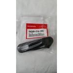
06240-ZY6-305 ARM, SHIFT
BF115DK1 LA, BF115DK1 XA, BF115DK1 XCA, BF135A4 LA, BF135A4 XA, BF135A4 XCA, BF135A5 LA, BF135A5 XA, BF135A5 XCA, BF135A6 LA, BF135A6 XA, BF135A6 XCA, BF135AK0 LA, BF135AK0 XA, BF135AK0 XCA, BF135AK2 LA, BF135AK2 XA, BF135AK2 XCA, BF150A4 LA, BF150A4
24612-ZY6-020
24612-ZY6-020 ARM, SHIFT (Honda Code 8675480).
BF135AK0 LA, BF135AK0 XA, BF135AK0 XCA, BF150AK0 LA, BF150AK0 XA, BF150AK0 XCA