90002-ZV5-821 BOLT, HEX. (5X30) (Honda Code 4594719). Honda
BF35AM LRTA, BF35AM XRTA, BF40AW LHTA, BF40AW LRTA, BF40AW XRTA, BF45AM LRTA, BF45AM SRTA, BF45AM XRTA, BF50AW LHTA, BF50AW LRTA, BF50AW XRTA
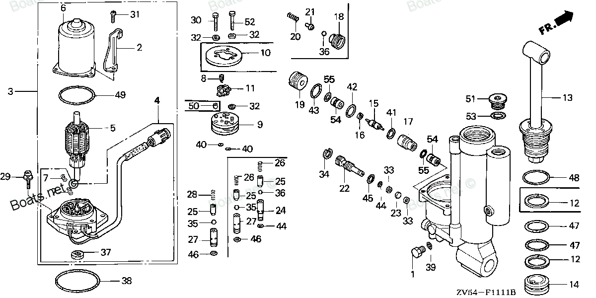
BOLT
 (Honda Code 4594719). Honda parts")
Price: query
Rating:
Number on catalog scheme: 30
Compatible models:
Honda entire parts catalog list:
- POWER TILT COMPONENTS » 90002-ZV5-821
- POWER TILT COMPONENTS » 90002-ZV5-821
- POWER TILT COMPONENTS » 90002-ZV5-821
- POWER TILT COMPONENTS » 90002-ZV5-821
- POWER TILT COMPONENTS » 90002-ZV5-821
- POWER TILT COMPONENTS » 90002-ZV5-821
- POWER TILT COMPONENTS » 90002-ZV5-821
- POWER TILT COMPONENTS » 90002-ZV5-821
- POWER TILT COMPONENTS » 90002-ZV5-821
- POWER TILT COMPONENTS » 90002-ZV5-821
- POWER TILT COMPONENTS » 90002-ZV5-821
- POWER TILT COMPONENTS » 90002-ZV5-821
- POWER TILT COMPONENTS » 90002-ZV5-821
- POWER TILT COMPONENTS » 90002-ZV5-821
- POWER TILT COMPONENTS » 90002-ZV5-821
- POWER TILT COMPONENTS » 90002-ZV5-821
- POWER TILT COMPONENTS » 90002-ZV5-821
- POWER TILT COMPONENTS » 90002-ZV5-821
- POWER TILT COMPONENTS » 90002-ZV5-821
- POWER TILT COMPONENTS » 90002-ZV5-821
- POWER TILT COMPONENTS » 90002-ZV5-821
- POWER TILT COMPONENTS » 90002-ZV5-821
Information:
Table 1
Required Tools
Tool Part Number Part Description Qty
A 298-5564 T40 Torx Socket 1
B 268-1968 Pry Bar 1
C 370-8376 Capping Kit 1 Start By:
Remove the rocker shaft assembly. Refer to Disassembly and Assembly, "Rocker Shaft - Remove" for the correct procedure.
Remove the fuel injection lines. Refer to Disassembly and Assembly, "Fuel Injection Lines - Remove" for the correct procedure.
Contact with high pressure fuel may cause fluid penetration and burn hazards. High pressure fuel spray may cause a fire hazard. Failure to follow these inspection, maintenance and service instructions may cause personal injury or death.
Ensure that all adjustments and repairs that are carried out to the fuel system are performed by authorised personnel that have the correct training.Before begining ANY work on the fuel system, refer to Operation and Maintenance Manual, "General Hazard Information and High Pressure Fuel Lines" for safety information.Refer to Systems Operation, Testing and Adjusting Manual, "Cleanliness of Fuel System Components" for detailed information on the standards of cleanliness that must be observed during ALL work on the fuel system.
Care must be taken to ensure that fluids are contained during performance of inspection, maintenance, testing, adjusting and repair of the product. Be prepared to collect the fluid with suitable containers before opening any compartment or disassembling any component containing fluids.Dispose of all fluids according to local regulations and mandates.
Use a deep socket in order to remove the electrical connections from the electronic unit injectors. Use of incorrect tooling will result in damage to the electronic unit injectors.
Note: Place identification marks on all hoses, on all hose assemblies, on wires and on all tube assemblies for installation purposes. Plug all hose assemblies and tube assemblies. Plugging all hose assemblies and tube assemblies will prevent fluid loss. Plugging all hose assemblies and tube assemblies will to keep contaminants from entering the system.
Turn the fuel supply to the OFF position.
Turn the battery disconnect switch to the OFF position.
Illustration 1 g01971774
Place a suitable container below tube assembly (1) in order to catch any fuel that might be spilled.
Loosen the nut on hose assembly (3) in order to allow the fuel to drain from tube assembly (1).
Remove hose assembly (3) from tube assembly (1). Remove O-ring seal (2).
Use Tooling (C) in order to cap the hose assembly immediately. Use Tooling (C) in order to plug the tube assembly immediately.
Illustration 2 g01971773
Make a temporary mark on valve bridges (5) in order to show the location and orientation. Remove valve bridges (5). Note: Identification will ensure that the valve bridges can be reinstalled in the original location and the original orientation.
Remove seal (4) from the cylinder head and electronic unit injector (8).
Make a temporary mark on wiring harness assembly (6) in order to show the location and orientation.
Use a deep socket to remove connections (7) from electronic unit injector (8).
Use Tooling (A) in order to remove Torx screw (9) from clamp (10). Discard the Torx screw. Note: Tooling (A) must be used to ensure no damage to the electronic unit injector.
Illustration 3 g01971775
Illustration 4 g01972153
Make a temporary mark on electronic unit injector (8) in order to show the original location of the electronic unit injector.
Temporarily remove Tooling (C) from the electronic unit injector.
Use Tooling (B) to pry beneath clamp (10) and free electronic unit injector (8) from the cylinder head. Note: Always handle electronic unit injectors with care.
Immediately replace Tooling (C) onto the electronic unit injector.
If electronic unit injector (8) is to be reused, Follow Step 17 through Step 19 in order to remove sealing washer (12) and O-ring seal (11).
Use a suitable tool in order to remove sealing washer (12) from electronic unit injector (8). Ensure that the sealing washer is removed from the cylinder head. Note: Ensure that the nozzle for the electronic unit injector is not damaged in any way on removal of the sealing washer.
Install Tooling (C) to the nozzle for electronic unit injector (8) and the open port of the electronic unit injector.
Remove O-ring seal (11) from electronic unit injector (8).
If necessary, repeat Step 7 through Step 19 in order to remove the remaining electronic unit injector.
Illustration 5 g02311716
If necessary, follow Steps 21.a through 21.f in order to remove harness assemblies (6) from cylinder head (16).
Cut cable straps (13).
Unscrew the remai
Parts bolt Honda:
90017-ZV0-000

90017-ZV0-000 BOLT, FLANGE (6X18) (Honda Code 1816370).
BF25A1 LHA, BF25A1 LHSA, BF25A1 LRSA, BF25A1 SHA, BF25A1 SHSA, BF25A1 SRSA, BF25A1 XRSA, BF25A2 LHA, BF25A2 LHSA, BF25A2 LRSA, BF25A2 SHA, BF25A2 SHSA, BF25A2 SRSA, BF25A2 XRSA, BF25AW LHA, BF25AW LHSA, BF25AW LRSA, BF25AW SHA, BF25AW SHSA, BF25AW SR
90013-ZV0-000

90013-ZV0-000 BOLT, FLANGE (6X12) (Honda Code 1816354).
BF115A1 LCA, BF115A1 XCA, BF115AX LA, BF115AX LCA, BF115AX XA, BF115AX XCA, BF115AY LA, BF115AY LCA, BF115AY XA, BF115AY XCA, BF130A1 LA, BF130A1 XA, BF130AX LA, BF130AX LCA, BF130AX XA, BF130AX XCA, BF130AY LA, BF130AY LCA, BF130AY XA, BF130AY XCA,
90105-ZV4-650

90105-ZV4-650 BOLT, OIL CHECK (8X8) (Honda Code 3744802).
BF115A1 LA, BF115A1 LCA, BF115A1 XA, BF115A1 XCA, BF115A2 LA, BF115A2 LCA, BF115A2 XA, BF115A2 XCA, BF115A3 LA, BF115A3 LCA, BF115A3 XA, BF115A3 XCA, BF115A4 LA, BF115A4 LCA, BF115A4 XA, BF115A4 XCA, BF115A5 LA, BF115A5 LCA, BF115A5 XA, BF115A5 XCA,
90020-ZV5-000
90020-ZV5-000 BOLT, FLANGE (6X22) (Honda Code 3705696).
BF25A1 LHA, BF25A1 LHSA, BF25A1 LRSA, BF25A1 SHA, BF25A1 SHSA, BF25A1 SRSA, BF25A1 XRSA, BF25A2 LHA, BF25A2 LHSA, BF25A2 LRSA, BF25A2 SHA, BF25A2 SHSA, BF25A2 SRSA, BF25A2 XRSA, BF25AW LHA, BF25AW LHSA, BF25AW LRSA, BF25AW SHA, BF25AW SHSA, BF25AW SR
95701-06040-02
95701-06040-02 BOLT, FLANGE (6X40) (Honda Code 3707130).
BF115A1 LA, BF115A1 LCA, BF115A1 XA, BF115A1 XCA, BF115A2 LA, BF115A2 LCA, BF115A2 XA, BF115A2 XCA, BF115AX LA, BF115AX LCA, BF115AX XA, BF115AX XCA, BF115AY LA, BF115AY LCA, BF115AY XA, BF115AY XCA, BF130A1 LA, BF130A1 LCA, BF130A1 XA, BF130A1 XCA,
90126-ZV5-000
90126-ZV5-000 BOLT, HEX. (8X20) (Honda Code 3705902).
BF25A1 LHA, BF25A1 LHSA, BF25A1 LRSA, BF25A1 SHA, BF25A1 SHSA, BF25A1 SRSA, BF25A1 XRSA, BF25A2 LHA, BF25A2 LHSA, BF25A2 LRSA, BF25A2 SHA, BF25A2 SHSA, BF25A2 SRSA, BF25A2 XRSA, BF25A3 LHA, BF25A3 LHSA, BF25A3 LRSA, BF25A3 SHA, BF25A3 SHSA, BF25A3 SR
90011-ZV5-003
90011-ZV5-003 BOLT, TORX (6X14) (Honda Code 3705647).
BF25A1 LHA, BF25A1 LHSA, BF25A1 LRSA, BF25A1 SHA, BF25A1 SHSA, BF25A1 SRSA, BF25A1 XRSA, BF25A2 LHA, BF25A2 LHSA, BF25A2 LRSA, BF25A2 SHA, BF25A2 SHSA, BF25A2 SRSA, BF25A2 XRSA, BF25A3 LHA, BF25A3 LHSA, BF25A3 LRSA, BF25A3 SHA, BF25A3 SHSA, BF25A3 SR
90101-ZV5-003

90101-ZV5-003 BOLT, SPECIAL (10X130) (Honda Code 3705720).
BF25A1 LHA, BF25A1 LHSA, BF25A1 LRSA, BF25A1 SHA, BF25A1 SHSA, BF25A1 SRSA, BF25A1 XRSA, BF25A2 LHA, BF25A2 LHSA, BF25A2 LRSA, BF25A2 SHA, BF25A2 SHSA, BF25A2 SRSA, BF25A2 XRSA, BF25A3 LHA, BF25A3 LHSA, BF25A3 LRSA, BF25A3 SHA, BF25A3 SHSA, BF25A3 SR