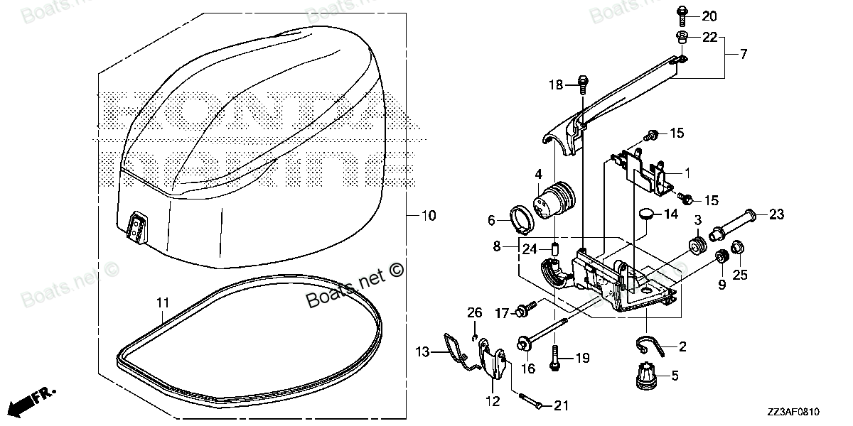
32581-ZZ3-000 BRACKET, REMOTE CONTROL CABLE Honda
BF60AK1 LRTA, BF60AK1 XRTA, BFP60AK1 LRTA, BFP60AK1 LRTB, BFP60AK1 XRTA
BRACKET

Price: query
Rating:
You can buy parts:
As an associate, we earn commssions on qualifying purchases through the links below

$29.03
24-09-2017
3.00[1.35] pounds
Honda: Honda
Honda 32581-ZZ3-000 Bracket; 32581ZZ3000 Made by Honda
HomeImprovement
HomeImprovement
Number on catalog scheme: 1
Compatible models:
Honda entire parts catalog list:
- ENGINE COVER » 32581-ZZ3-000
- ENGINE COVER » 32581-ZZ3-000
- ENGINE COVER » 32581-ZZ3-000
- ENGINE COVER » 32581-ZZ3-000
- ENGINE COVER » 32581-ZZ3-000
Information:
START BY:a) remove timing gear cover Before any timing gears are removed make sure "C" mark (2) on the crankshaft gear is in alignment with "C" mark (1) on the camshaft gear. 1. Loosen bolt (3). Leave a gap of 3.2 mm (.125 in.) between washer and fuel pump drive gear (4). 2. Install tooling (A) and loosen the fuel pump drive gear (4) from the fuel injection pump camshaft. Remove bolt (3), washer and gear (4). 3. Remove bolts, plate (6) and the fuel pump idler gear (5). 4. Remove bearing (7) from the gear (5) with tooling (B). 5. Remove four bolts (9) and camshaft gear (8).Install Timing Gears
1. Install camshaft gear (1) with the "C" mark on the camshaft gear in alignment with the "C" mark on the crankshaft gear (2) as shown in the illustration. Install and tighten bolts to a torque of 55 7 N m (41 5 lb.ft.). 2. Use tooling (A) to install the bearing in idler gear (3). The end of the bearing must be 1.52 0.25 mm (.060 .010 in.) below the face of the gear hub. 3. Be sure the oil hole in shaft for gear (3) is open. Install fuel pump idler gear (3) on the shaft. Install plate (4) in position with the finished side toward the gear. 4. Install fuel pump drive gear (5) on fuel pump camshaft. Install washer and bolt (6) but do not tighten.5. To be sure that the timing of the fuel pump drive gear (5) is correct with the crankshaft and camshaft gears, use the following procedure to put the No. 1 piston top center on the compression stroke. No 1 piston at top center (TC) on the compression stroke is the starting point for all timing procedures:a) Remove the plug from the flywheel housing and remove the breather from the valve cover. b) Remove the starting motor and install tool (B).c) Turn the crankshaft clockwise (as seen from the front of the engine) until tool (D) can be installed in the flywheel through the opening for the plug.d) If you go past the bolt hole in the flywheel, turn the crankshaft counterclockwise opposite the direction of engine rotation (as seen from the front of the engine) approximately 30 degrees. This procedure will permit the (backlash) gear clearance to be removed from the timing gears when the crankshaft is turned in the direction of engine rotation (clockwise). Do not turn the crankshaft counterclockwise to get bolt hole alignment. The rocker arms for No. 1 piston can be seen through the breather hole in the valve cover.e) Check to see if both rocker arms for the No. 1 piston can be moved by hand (have clearance with the valve stem). The No. 1 piston is at top center on the compression stroke when the bolt can be put in the flywheel through the hole in the flywheel housing, and both rocker arms for the No. 1 piston can be moved by hand (have clearance with the valve stem).f) If both rocker arms can not be moved by hand, the No. 1 piston is not at top center on the compression stroke. Remove tool (D) from the flywheel and turn the crankshaft clockwise (as seen from the front of the engine) one full turn (360°). Install tool (D) in the flywheel again. Check to see if both rocker arms seen through breather hole can be moved by hand. g) Install tool (C) in the fuel injection pump housing as shown. Push on tool (C) and turn fuel injection pump camshaft. When tool (C) engages the groove (slot) in the fuel injection pump camshaft, the fuel injection pump in the No. 1 piston top center position. 6. Install tooling (E).7. Use a 9S7352 Torque Wrench (7) to put a clockwise force of 68 N m (50 lb.ft.) on tooling (C) while bolt that holds the weight is tightened with a 5P7425 Torque Wrench (8) to a torque of 270 25 N m (200 18 lb.ft.).8. Check the timing to make sure it is correct:a) Remove the timing pin (C) from the pump camshaft and the bolt from the flywheel.b) Turn the crankshaft clockwise (as seen from the front of the engine) approximately 1/2 turn. Install the timing pin again.c) While the crankshaft is turned clockwise (as seen from the front of the engine), push on the timing pin (C) until it engages the groove (slot) in the pump camshaft.d) Install the bolt in the flywheel. The timing is correct when the bolt is installed in the flywheel and the timing pin (C) is installed in the groove (slot) in the pump camshaft.9. Remove tool (C) from the fuel injection pump and tooling (B) from flywheel housing. Install plug and the electric starting motor.10. Install breather assembly on the valve cover.END BY:a) install timing cover
1. Install camshaft gear (1) with the "C" mark on the camshaft gear in alignment with the "C" mark on the crankshaft gear (2) as shown in the illustration. Install and tighten bolts to a torque of 55 7 N m (41 5 lb.ft.). 2. Use tooling (A) to install the bearing in idler gear (3). The end of the bearing must be 1.52 0.25 mm (.060 .010 in.) below the face of the gear hub. 3. Be sure the oil hole in shaft for gear (3) is open. Install fuel pump idler gear (3) on the shaft. Install plate (4) in position with the finished side toward the gear. 4. Install fuel pump drive gear (5) on fuel pump camshaft. Install washer and bolt (6) but do not tighten.5. To be sure that the timing of the fuel pump drive gear (5) is correct with the crankshaft and camshaft gears, use the following procedure to put the No. 1 piston top center on the compression stroke. No 1 piston at top center (TC) on the compression stroke is the starting point for all timing procedures:a) Remove the plug from the flywheel housing and remove the breather from the valve cover. b) Remove the starting motor and install tool (B).c) Turn the crankshaft clockwise (as seen from the front of the engine) until tool (D) can be installed in the flywheel through the opening for the plug.d) If you go past the bolt hole in the flywheel, turn the crankshaft counterclockwise opposite the direction of engine rotation (as seen from the front of the engine) approximately 30 degrees. This procedure will permit the (backlash) gear clearance to be removed from the timing gears when the crankshaft is turned in the direction of engine rotation (clockwise). Do not turn the crankshaft counterclockwise to get bolt hole alignment. The rocker arms for No. 1 piston can be seen through the breather hole in the valve cover.e) Check to see if both rocker arms for the No. 1 piston can be moved by hand (have clearance with the valve stem). The No. 1 piston is at top center on the compression stroke when the bolt can be put in the flywheel through the hole in the flywheel housing, and both rocker arms for the No. 1 piston can be moved by hand (have clearance with the valve stem).f) If both rocker arms can not be moved by hand, the No. 1 piston is not at top center on the compression stroke. Remove tool (D) from the flywheel and turn the crankshaft clockwise (as seen from the front of the engine) one full turn (360°). Install tool (D) in the flywheel again. Check to see if both rocker arms seen through breather hole can be moved by hand. g) Install tool (C) in the fuel injection pump housing as shown. Push on tool (C) and turn fuel injection pump camshaft. When tool (C) engages the groove (slot) in the fuel injection pump camshaft, the fuel injection pump in the No. 1 piston top center position. 6. Install tooling (E).7. Use a 9S7352 Torque Wrench (7) to put a clockwise force of 68 N m (50 lb.ft.) on tooling (C) while bolt that holds the weight is tightened with a 5P7425 Torque Wrench (8) to a torque of 270 25 N m (200 18 lb.ft.).8. Check the timing to make sure it is correct:a) Remove the timing pin (C) from the pump camshaft and the bolt from the flywheel.b) Turn the crankshaft clockwise (as seen from the front of the engine) approximately 1/2 turn. Install the timing pin again.c) While the crankshaft is turned clockwise (as seen from the front of the engine), push on the timing pin (C) until it engages the groove (slot) in the pump camshaft.d) Install the bolt in the flywheel. The timing is correct when the bolt is installed in the flywheel and the timing pin (C) is installed in the groove (slot) in the pump camshaft.9. Remove tool (C) from the fuel injection pump and tooling (B) from flywheel housing. Install plug and the electric starting motor.10. Install breather assembly on the valve cover.END BY:a) install timing cover
Parts bracket Honda:
50527-ZV5-000
50527-ZV5-000 BRACKET, TILTING (Honda Code 3704996).
BF35AM LHA, BF35AM LRA, BF35AM LRTA, BF35AM SHA, BF35AM XRTA, BF40A1 LHA, BF40A1 LHTA, BF40A1 LRA, BF40A1 LRTA, BF40A1 XRTA, BF40A2 LHA, BF40A2 LHTA, BF40A2 LRA, BF40A2 LRTA, BF40A2 XRTA, BF40A3 LHA, BF40A3 LHTA, BF40A3 LRA, BF40A3 LRTA, BF40A3 XRTA,
24865-ZV5-000
24865-ZV5-000 BRACKET, LINK JOINT (Honda Code 3703220).
BF115A1 LA, BF115A1 LCA, BF115A1 XA, BF115A1 XCA, BF115A2 LA, BF115A2 LCA, BF115A2 XA, BF115A2 XCA, BF115A3 LA, BF115A3 LCA, BF115A3 XA, BF115A3 XCA, BF115A4 LA, BF115A4 LCA, BF115A4 XA, BF115A4 XCA, BF115A5 LA, BF115A5 LCA, BF115A5 XA, BF115A5 XCA,
37256-ZV5-821
37256-ZV5-821 BRACKET (Honda Code 3704210).
BF115A1 LA, BF115A1 LCA, BF115A1 XA, BF115A1 XCA, BF115A2 LA, BF115A2 LCA, BF115A2 XA, BF115A2 XCA, BF115A3 LA, BF115A3 LCA, BF115A3 XA, BF115A3 XCA, BF115A4 LA, BF115A4 LCA, BF115A4 XA, BF115A4 XCA, BF115A5 LA, BF115A5 LCA, BF115A5 XA, BF115A5 XCA,
37266-ZV5-821
37266-ZV5-821 BRACKET (Honda Code 3704251).
BF115A1 LA, BF115A1 LCA, BF115A1 XA, BF115A1 XCA, BF115A2 LA, BF115A2 LCA, BF115A2 XA, BF115A2 XCA, BF115A3 LA, BF115A3 LCA, BF115A3 XA, BF115A3 XCA, BF115A4 LA, BF115A4 LCA, BF115A4 XA, BF115A4 XCA, BF115A5 LA, BF115A5 LCA, BF115A5 XA, BF115A5 XCA,
24819-ZW5-U01
24819-ZW5-U01 BRACKET, REMOTE CONTROL (Honda Code 6799647). HOUSING
BF115A1 LA, BF115A1 LCA, BF115A1 XA, BF115A1 XCA, BF115A2 LA, BF115A2 LCA, BF115A2 XA, BF115A2 XCA, BF115A3 LA, BF115A3 LCA, BF115A3 XA, BF115A3 XCA, BF115A4 LA, BF115A4 LCA, BF115A4 XA, BF115A4 XCA, BF115A5 LA, BF115A5 LCA, BF115A5 XA, BF115A5 XCA,
38582-ZZ3-000
38582-ZZ3-000 BRACKET, MAIN RELAY
BF60AK1 LRTA, BF60AK1 XRTA, BFP60AK1 LRTA, BFP60AK1 LRTB, BFP60AK1 XRTA
40155-ZZ3-000
40155-ZZ3-000 BRACKET, RR. COVER (LOWER)
BF60AK1 LRTA, BF60AK1 XRTA, BFP60AK1 LRTA, BFP60AK1 LRTB, BFP60AK1 XRTA
36122-ZZ3-003