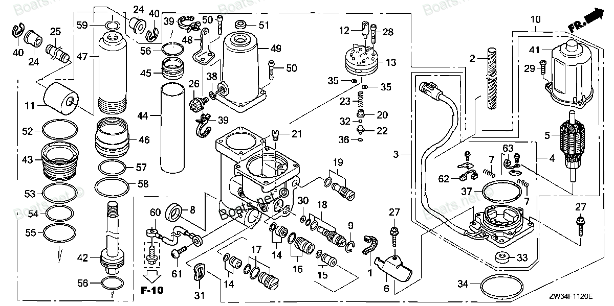
36125-ZW4-H11 CLAMP, WIRE (Honda Code 7531726). Honda
BF40A4 LHTA, BF40A4 LRTA, BF40A5 LHTA, BF40A5 LRTA, BF40A6 LHTA, BF40A6 LRTA, BF40AK0 LRTA, BF40DK2 LRTA, BF50A4 LHTA, BF50A4 LRTA, BF50A4 SRJA, BF50A4 XRTA, BF50A5 LHTA, BF50A5 LRTA, BF50A5 SRJA, BF50A5 XRTA, BF50A6 LHTA, BF50A6 LRTA, BF50A6 SRJA, B
CLAMP
. Honda parts")
Price: query
Rating:
Number on catalog scheme: 6
Compatible models:
BF40A4 LHTA
BF40A4 LRTA
BF40A5 LHTA
BF40A5 LRTA
BF40A6 LHTA
BF40A6 LRTA
BF40AK0 LRTA
BF40DK2 LRTA
BF50A4 LHTA
BF50A4 LRTA
BF50A4 SRJA
BF50A4 XRTA
BF50A5 LHTA
BF50A5 LRTA
BF50A5 SRJA
BF50A5 XRTA
BF50A6 LHTA
BF50A6 LRTA
BF50A6 SRJA
BF50A6 XRTA
BF50AK0 LRTA
BF50AK0 SRJA
BF50AK0 XRTA
BF50DK2 LRTA
BF50DK2 XRTA
BF60AK1 LRTA
BF60AK1 XRTA
BFP60AK1 LRTA
BFP60AK1 LRTB
BFP60AK1 XRTA
Honda
Honda entire parts catalog list:
- POWER TRIM-TILT » 36125-ZW4-H11
- POWER TRIM-TILT » 36125-ZW4-H11
- POWER TRIM-TILT » 36125-ZW4-H11
- POWER TRIM-TILT » 36125-ZW4-H11
- POWER TRIM-TILT » 36125-ZW4-H11
- POWER TRIM-TILT » 36125-ZW4-H11
- POWER TRIM-TILT » 36125-ZW4-H11
- POWER TRIM-TILT » 36125-ZW4-H11
- POWER TRIM-TILT » 36125-ZW4-H11
- POWER TRIM-TILT » 36125-ZW4-H11
- POWER TRIM-TILT » 36125-ZW4-H11
- POWER TRIM-TILT » 36125-ZW4-H11
- POWER TRIM-TILT » 36125-ZW4-H11
- POWER TRIM-TILT » 36125-ZW4-H11
- POWER TRIM-TILT » 36125-ZW4-H11
- POWER TRIM-TILT » 36125-ZW4-H11
- POWER TRIM-TILT » 36125-ZW4-H11
- POWER TRIM-TILT » 36125-ZW4-H11
- POWER TRIM-TILT » 36125-ZW4-H11
- POWER TRIM-TILT » 36125-ZW4-H11
- POWER TRIM-TILT » 36125-ZW4-H11
- POWER TRIM-TILT » 36125-ZW4-H11
- POWER TRIM-TILT » 36125-ZW4-H11
- POWER TRIM-TILT » 36125-ZW4-H11
- POWER TRIM-TILT » 36125-ZW4-H11
- POWER TRIM-TILT » 36125-ZW4-H11
- POWER TRIM-TILT » 36125-ZW4-H11
- POWER TRIM-TILT » 36125-ZW4-H11
- POWER TRIM-TILT » 36125-ZW4-H11
- POWER TRIM-TILT » 36125-ZW4-H11
Information:
start by: a) remove fuel injection nozzles Do not disassemble any nozzle until testing has shown that disassembly is needed. Check each nozzle with tool (A) for leakage, opening pressure, and the shape and amount of fuel (spray pattern) coming out of the nozzle. Do not clean or make an adjustment to any nozzle that has a large (excessive) amount of return leakage. Excessive return leakage can be an indication of nozzle failures that can not be corrected with an adjustment or cleaning and can cause engine damage. See TESTING 9L7883 FUEL INJECTION NOZZLES in TESTING AND ADJUSTING.
Keep the work area and all tools extra clean. Be careful not to cause damage to the parts during disassembly and assembly of the nozzles.
1. Put the nozzle in tool (B). Put tool (B) and the nozzle in a vise. Do not put any part of a nozzle directly in a vise. Loosen locknut (1). 2. Loosen adjusting screw (2) approximately three turns. Loosen pressure screw (3). 3. While holding the nozzle in one hand, tilt the nozzle and remove the pressure adjusting screw and locknut, shims, spring, seat, and valve. 4. If the valve does not slide out of the nozzle, install tool (C) and remove valve as follows: a) Push valve into nozzle with tool (C) until valve is against bottom of nozzle.b) Push down on body of tool (C) to engage collet on valve with tool (C).c) Turn nut counterclockwise and remove valve from the nozzle body.5. Put the parts in solvent to loosen carbon and deposits of foreign material. The body is assembled with an epoxy material and must not be in contact with the solvent for more than one to two hours. See SPECIAL INSTRUCTION FORM NO. FM055225 for the correct method of cleaning the nozzle.Assemble Fuel Injection Nozzles (9L7883 Nozzles)
Make sure all of the parts have been thoroughly cleaned before assembling the nozzles. Flush the body to remove any debris or lapping compound.1. Put clean fuel on all of the parts. 2. Put valve (1) in position in the body as shown.3. Install adjusting screw (7) into pressure screw (5). Turn the adjusting screw two or three turns and install locknut (6). Do not tighten the locknut.4. Put shims (4), spring (3), and seat (2) in position on the adjusting screw. The thicker shim of shims (4) must be against the screw.5. Put seat (2) in contact with the valve and push the valve into position in the body. Tighten the pressure screw by hand. 6. Put the nozzle in position in tool (A). Put tool (A) and the nozzle in a vise. Tighten the pressure screw to a torque of 70 to 80 lb.in. (80.7 to 92.2 cm.kg).7. Check the opening pressure of the nozzle as controlled by shims (4) with tool (B). See TESTING 9L7883 FUEL INJECTION NOZZLES, OPENING PRESSURE TEST in TESTING AND ADJUSTING.8. Check the valve lift adjustment as controlled by adjusting screw (7) with tool (B). See TESTING 9L7883 FUEL INJECTION NOZZLES, VALVE LIFT ADJUSTMENT in TESTING AND ADJUSTING. 9. Hold the adjusting screw with a screwdriver and tighten the locknut until the adjusting screw will not turn.10. Tighten the locknut to a torque of 35 to 45 lb.in. (40.4 to 51.9 cm.kg).end by: a) install fuel injection nozzles
Parts clamp Honda:
16223-ZV5-000

16223-ZV5-000 CLAMP, FUEL TUBE (A) (Honda Code 3701935).
BF25A1 LHA, BF25A1 LHSA, BF25A1 LRSA, BF25A1 SHA, BF25A1 SHSA, BF25A1 SRSA, BF25A1 XRSA, BF25A2 LHA, BF25A2 LHSA, BF25A2 LRSA, BF25A2 SHA, BF25A2 SHSA, BF25A2 SRSA, BF25A2 XRSA, BF25A3 LHA, BF25A3 LHSA, BF25A3 LRSA, BF25A3 SHA, BF25A3 SHSA, BF25A3 SR
32660-MJ6-710

32660-MJ6-710 CLAMP, WIRE (Honda Code 3703907).
BF115A1 LA, BF115A1 LCA, BF115A1 XA, BF115A1 XCA, BF115A2 LA, BF115A2 LCA, BF115A2 XA, BF115A2 XCA, BF115A3 LA, BF115A3 LCA, BF115A3 XA, BF115A3 XCA, BF115A4 LA, BF115A4 LCA, BF115A4 XA, BF115A4 XCA, BF115A5 LA, BF115A5 LCA, BF115A5 XA, BF115A5 XCA,
37215-KM1-670
37215-KM1-670 CLAMP (Honda Code 2047215).
BF115A1 LA, BF115A1 LCA, BF115A1 XA, BF115A1 XCA, BF115A2 LA, BF115A2 LCA, BF115A2 XA, BF115A2 XCA, BF115A3 LA, BF115A3 LCA, BF115A3 XA, BF115A3 XCA, BF115A4 LA, BF115A4 LCA, BF115A4 XA, BF115A4 XCA, BF115A5 LA, BF115A5 LCA, BF115A5 XA, BF115A5 XCA,
90601-ZV3-030
90601-ZV3-030 CLAMP, TUBE (D17)
BF115DK1 LA, BF115DK1 XA, BF115DK1 XCA, BF135A4 LA, BF135A4 XA, BF135A4 XCA, BF135A5 LA, BF135A5 XA, BF135A5 XCA, BF135A6 LA, BF135A6 XA, BF135A6 XCA, BF135AK0 LA, BF135AK0 XA, BF135AK0 XCA, BF135AK2 LA, BF135AK2 XA, BF135AK2 XCA, BF150A4 LA, BF150A4
12328-ZZ5-000
16895-ZZ5-003
16446-Z0G-003
16446-Z0G-003 CLAMP, FUEL TUBE
BF60AK1 LRTA, BF60AK1 XRTA, BFP60AK1 LRTA, BFP60AK1 LRTB, BFP60AK1 XRTA
53103-ZZ3-A41
53103-ZZ3-A41 CLAMP, SHIFT CABLE
BF60AK1 LRTA, BF60AK1 XRTA, BFP60AK1 LRTA, BFP60AK1 LRTB, BFP60AK1 XRTA