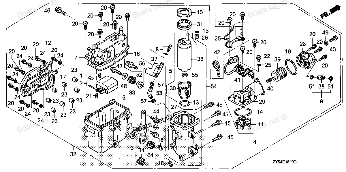
91501-ZY3-000 COLLAR (8.3X14.5) Honda
BF135A4 LA, BF135A4 XA, BF135A4 XCA, BF135A5 LA, BF135A5 XA, BF135A5 XCA, BF135A6 LA, BF135A6 XA, BF135A6 XCA, BF150A4 LA, BF150A4 XA, BF150A4 XCA, BF150A5 LA, BF150A5 XA, BF150A5 XCA, BF150A6 LA, BF150A6 XA, BF150A6 XCA, BF200A2 LA, BF200A2 XA, BF20
COLLAR
 Honda parts")
Price: query
Rating:
Number on catalog scheme: 52
Compatible models:
BF135A4 LA
BF135A4 XA
BF135A4 XCA
BF135A5 LA
BF135A5 XA
BF135A5 XCA
BF135A6 LA
BF135A6 XA
BF135A6 XCA
BF150A4 LA
BF150A4 XA
BF150A4 XCA
BF150A5 LA
BF150A5 XA
BF150A5 XCA
BF150A6 LA
BF150A6 XA
BF150A6 XCA
BF200A2 LA
BF200A2 XA
BF200A2 XCA
BF200A2 XXA
BF200A2 XXCA
BF200A3 LA
BF200A3 XA
BF200A3 XCA
BF200A3 XXA
BF200A3 XXCA
BF225A2 LA
BF225A2 XA
BF225A2 XCA
BF225A2 XXA
BF225A2 XXCA
BF225A3 LA
BF225A3 XA
BF225A3 XCA
BF225A3 XXA
BF225A3 XXCA
Honda
Honda entire parts catalog list:
- VAPOR SEPARATOR ASSY » 91501-ZY3-000
- VAPOR SEPARATOR ASSY. » 91501-ZY3-000
- VAPOR SEPARATOR ASSY. » 91501-ZY3-000
- VAPOR SEPARATOR ASSY. » 91501-ZY3-000
- VAPOR SEPARATOR ASSY. » 91501-ZY3-000
- VAPOR SEPARATOR ASSY. » 91501-ZY3-000
- VAPOR SEPARATOR ASSY. » 91501-ZY3-000
- VAPOR SEPARATOR ASSY. » 91501-ZY3-000
- VAPOR SEPARATOR ASSY. » 91501-ZY3-000
- VAPOR SEPARATOR ASSY. » 91501-ZY3-000
- VAPOR SEPARATOR ASSY. » 91501-ZY3-000
- VAPOR SEPARATOR ASSY. » 91501-ZY3-000
- VAPOR SEPARATOR ASSY. » 91501-ZY3-000
- VAPOR SEPARATOR ASSY. » 91501-ZY3-000
- VAPOR SEPARATOR ASSY. » 91501-ZY3-000
- VAPOR SEPARATOR ASSY. » 91501-ZY3-000
- VAPOR SEPARATOR ASSY. » 91501-ZY3-000
- VAPOR SEPARATOR ASSY. » 91501-ZY3-000
- VAPOR SEPARATOR ASSY. » 91501-ZY3-000
- VAPOR SEPARATOR ASSY » 91501-ZY3-000
- VAPOR SEPARATOR ASSY. » 91501-ZY3-000
- VAPOR SEPARATOR ASSY. » 91501-ZY3-000
- VAPOR SEPARATOR ASSY » 91501-ZY3-000
- VAPOR SEPARATOR ASSY » 91501-ZY3-000
- VAPOR SEPARATOR ASSY. » 91501-ZY3-000
- VAPOR SEPARATOR ASSY. » 91501-ZY3-000
- VAPOR SEPARATOR ASSY » 91501-ZY3-000
- VAPOR SEPARATOR ASSY » 91501-ZY3-000
- VAPOR SEPARATOR ASSY. » 91501-ZY3-000
- VAPOR SEPARATOR ASSY » 91501-ZY3-000
- VAPOR SEPARATOR ASSY. » 91501-ZY3-000
- VAPOR SEPARATOR ASSY. » 91501-ZY3-000
- VAPOR SEPARATOR ASSY » 91501-ZY3-000
- VAPOR SEPARATOR ASSY » 91501-ZY3-000
- VAPOR SEPARATOR ASSY. » 91501-ZY3-000
- VAPOR SEPARATOR ASSY » 91501-ZY3-000
- VAPOR SEPARATOR ASSY. » 91501-ZY3-000
- VAPOR SEPARATOR ASSY. » 91501-ZY3-000
- VAPOR SEPARATOR ASSY » 91501-ZY3-000
- VAPOR SEPARATOR ASSY » 91501-ZY3-000
- VAPOR SEPARATOR ASSY. » 91501-ZY3-000
- VAPOR SEPARATOR ASSY. » 91501-ZY3-000
- VAPOR SEPARATOR ASSY » 91501-ZY3-000
- VAPOR SEPARATOR ASSY » 91501-ZY3-000
- VAPOR SEPARATOR ASSY. » 91501-ZY3-000
- VAPOR SEPARATOR ASSY » 91501-ZY3-000
- VAPOR SEPARATOR ASSY. » 91501-ZY3-000
- VAPOR SEPARATOR ASSY. » 91501-ZY3-000
- VAPOR SEPARATOR ASSY » 91501-ZY3-000
- VAPOR SEPARATOR ASSY » 91501-ZY3-000
- VAPOR SEPARATOR ASSY. » 91501-ZY3-000
- VAPOR SEPARATOR ASSY » 91501-ZY3-000
- VAPOR SEPARATOR ASSY. » 91501-ZY3-000
- VAPOR SEPARATOR ASSY. » 91501-ZY3-000
- VAPOR SEPARATOR ASSY » 91501-ZY3-000
- VAPOR SEPARATOR ASSY » 91501-ZY3-000
- VAPOR SEPARATOR ASSY. » 91501-ZY3-000
- VAPOR SEPARATOR ASSY. » 91501-ZY3-000
- VAPOR SEPARATOR ASSY » 91501-ZY3-000
Information:
Use this procedure to troubleshoot the position sensors for the following valves:
EGR valve
Engine intake throttle valve
Turbocharger electronic wastegateEach position sensor is integral in the associated valve. If the following procedure indicates a fault with the position sensor, then the entire valve must be replaced.The following background information is related to this procedure:The troubleshooting procedures for the diagnostic codes of each position sensor are identical. The 5 VDC sensor supply provides power to all 5 VDC sensors. The sensor supply is output short circuit protected. A short circuit to the battery will not damage the circuit inside the ECM. The signal voltage from the valve position sensors is supplied to the appropriate terminal at the P1 or P2 ECM connector.Pull-up VoltageThe ECM continuously outputs a pull-up voltage on the circuit for the sensor signal wire. The ECM uses this pull-up voltage to detect an open in the signal circuit. When the ECM detects a voltage above a threshold, the ECM generates an open circuit diagnostic code (XXXX-3).If the sensor is disconnected, pull-up voltage indicates that the wires are not open or shorted to ground. The absence of pull-up voltage indicates an open in the signal wire or a short to ground. If the voltage is different from pull-up voltage, the signal wire is shorted to another wire in the harness.
Illustration 1 g06498479Complete the procedure in the order in which the steps are listed.
Table 2
Troubleshooting Test Steps Values Results
1. Verify All Active and Recently Logged Diagnostic Codes
A. Turn the keyswitch to the ON position.
B. Use the electronic service tool to perform the "Air System Motor Valves Verification Test".
C. Verify if any of the diagnostic codes that are listed in Table 1are active or recently logged.
Diagnostic codes
Result: None of the preceding diagnostic codes are active or recently logged.
Repair: The fault may be intermittent. Refer to Troubleshooting, "Electrical Connectors - Inspect" to identify intermittent faults.
Result: One or more of the preceding diagnostic codes are active or recently logged.
Proceed to Test Step 2.
2. Inspect Electrical Connectors and Wiring
A. Thoroughly inspect the connector for the suspect valve and the engine interface connector. Refer to Troubleshooting, "Electrical Connectors - Inspect".
B. Perform a 30 N (6.7 lb) pull test on each of the wires that are associated with the suspect position sensor in the valve connector and the engine interface connector.
C. Check the harness for abrasions and for pinch points from the suspect valve back to the ECM.
Note: Do not disconnect the ECM connector at this stage. The ECM can only be disconnected and reconnected 10 times before damage to the harness connector may occur.
Damaged wire or connector
Result: A damaged wire or damaged connector was found.
Repair: Repair the damaged wire or the damaged connector.
Use the electronic service tool to clear all logged diagnostic codes. Verify that the repair eliminates the fault.
Result: All connectors, pins, and sockets are correctly connected and/or inserted and the harness is free of corrosion, of abrasion or of pinch points.
Proceed to Test Step 3.
3. Measure the Sensor Supply Voltage at the Valve Connector
A. Turn the keyswitch to the OFF position.
B. Disconnect the suspect valve from the engine harness.
C. Turn the keyswitch to the ON position.
D. Measure the voltage at the harness connector for the valve from the 5 VDC supply terminal of the position sensor to the sensor ground terminal.
Between 4.84 V and 5.16 V
Result: The measured voltage is not within the expected range.
Proceed to Test Step 4.
Result: The measured voltage is within the expected range.
Proceed to Test Step 5.
4. Measure the Supply Voltage at the Engine Interface Connector
A. Turn the keyswitch to the OFF position.
B. Disconnect the engine interface connector.
C. Turn the keyswitch to the ON position.
D. Use a suitable voltmeter to measure the voltage at the engine interface connector. Measure the voltage between the 5 VDC supply pin and the return pin for the suspect valve.
E. Reconnect the engine interface connector.
Between 4.84 V and 5.16 V
Result: The voltage is within the expected range.
The fault is in the 5 VDC supply wire or the ground wire between the valve connector and the engine interface connector.
Repair: Repair the faulty wiring or replace the faulty wiring.
Use the electronic service tool to clear all logged diagnostic codes and verify that the repair eliminates the fault.
Result: The voltage is not within the expected range.
The fault is in the 5 VDC supply wire or the ground wire between the engine interface connector and the ECM.
Repair: Repair the faulty wiring or replace the faulty wiring.
Use the electronic service tool to clear all logged diagnostic codes and verify that the repair eliminates the fault.
5. Verify the Type of Active Diagnostic Code
A. Turn the keyswitch to the ON position.
B. Use the electronic service tool to perform the "Air System Motor Valves Verification Test".
C. Use the electronic service tool to check for active diagnostic codes. Record all active diagnostic codes.
Diagnostic codes
Result: A -4 diagnostic code is active.
Proceed to Test Step 6.
Result: A -3 diagnostic code is active.
Proceed to Test Step 9.
6. Create an Open Circuit at the Valve Connector
A. Turn the keyswitch to the OFF position.
B. Disconnect the connector for the valve with the -4 diagnostic code.
C. Turn the keyswitch to the ON position.
D. Use the electronic service tool to perform the "Air System Motor Valves Verification Test". Check for an -3 diagnostic code.
E. Turn the keyswitch to the OFF position.
Diagnostic codes
Result: A -3 diagnostic code is active with the valve disconnected.
Repair: Reconnect the connector for the valve.
If the -4 diagnostic code returns, there is a short in the valve.
Install a replacement valve. Refer to Disassembly and Assembly for the correct procedure.
If the turbocharger EWG is replaced, use the electronic service tool to perform the "Turbocharger Wastegate Actuator Replacement Reset".
If the NRS valve is replaced, use the electronic service tool to perform the "EGR Valve Replacement Reset".
If th
Parts collar Honda:
91563-ZV5-000
91563-ZV5-000 COLLAR, DISTANCE (6X10.5X25) (Honda Code 3706900).
BF115A1 LA, BF115A1 LCA, BF115A1 XA, BF115A1 XCA, BF115A2 LA, BF115A2 LCA, BF115A2 XA, BF115A2 XCA, BF115A3 LA, BF115A3 LCA, BF115A3 XA, BF115A3 XCA, BF115A4 LA, BF115A4 LCA, BF115A4 XA, BF115A4 XCA, BF115A5 LA, BF115A5 LCA, BF115A5 XA, BF115A5 XCA,
24854-ZV5-000

24854-ZV5-000 COLLAR, SLIDING PLATE (Honda Code 3703196).
BF115A1 LA, BF115A1 LCA, BF115A1 XA, BF115A1 XCA, BF115A2 LA, BF115A2 LCA, BF115A2 XA, BF115A2 XCA, BF115A3 LA, BF115A3 LCA, BF115A3 XA, BF115A3 XCA, BF115A4 LA, BF115A4 LCA, BF115A4 XA, BF115A4 XCA, BF115A5 LA, BF115A5 LCA, BF115A5 XA, BF115A5 XCA,
91567-ZV5-000
91567-ZV5-000 COLLAR, LINK JOINT (Honda Code 3706918).
BF115A1 LA, BF115A1 LCA, BF115A1 XA, BF115A1 XCA, BF115A2 LA, BF115A2 LCA, BF115A2 XA, BF115A2 XCA, BF115A3 LA, BF115A3 LCA, BF115A3 XA, BF115A3 XCA, BF115A4 LA, BF115A4 LCA, BF115A4 XA, BF115A4 XCA, BF115A5 LA, BF115A5 LCA, BF115A5 XA, BF115A5 XCA,
91570-ZV5-000

91570-ZV5-000 COLLAR, DISTANCE (6X10X43.5) (Honda Code 3706942).
BF115A1 LA, BF115A1 LCA, BF115A1 XA, BF115A1 XCA, BF115A2 LA, BF115A2 LCA, BF115A2 XA, BF115A2 XCA, BF115A3 LA, BF115A3 LCA, BF115A3 XA, BF115A3 XCA, BF115A4 LA, BF115A4 LCA, BF115A4 XA, BF115A4 XCA, BF115A5 LA, BF115A5 LCA, BF115A5 XA, BF115A5 XCA,
91560-ZV5-000
91560-ZV5-000 COLLAR, STEERING ROD (Honda Code 3706892).
BF115A1 LA, BF115A1 LCA, BF115A1 XA, BF115A1 XCA, BF115A2 LA, BF115A2 LCA, BF115A2 XA, BF115A2 XCA, BF115A3 LA, BF115A3 LCA, BF115A3 XA, BF115A3 XCA, BF115A4 LA, BF115A4 LCA, BF115A4 XA, BF115A4 XCA, BF115A5 LA, BF115A5 LCA, BF115A5 XA, BF115A5 XCA,
91560-ZY3-000
91560-ZY3-000 COLLAR, STEERING ROD (Honda Code 6994727).
BF175AK1 LA, BF175AK1 XA, BF175AK1 XCA, BF175AK2 LA, BF175AK2 XA, BF175AK2 XCA, BF200A2 LA, BF200A2 XA, BF200A2 XCA, BF200A2 XXA, BF200A2 XXCA, BF200A3 LA, BF200A3 XA, BF200A3 XCA, BF200A3 XXA, BF200A3 XXCA, BF200A4 LA, BF200A4 XA, BF200A4 XCA, BF200
91551-ZY3-000
91551-ZY3-000 COLLAR, DISTANCE (Honda Code 6994701).
BF175AK1 LA, BF175AK1 XA, BF175AK1 XCA, BF175AK2 LA, BF175AK2 XA, BF175AK2 XCA, BF200A2 LA, BF200A2 XA, BF200A2 XCA, BF200A2 XXA, BF200A2 XXCA, BF200A3 LA, BF200A3 XA, BF200A3 XCA, BF200A3 XXA, BF200A3 XXCA, BF200A4 LA, BF200A4 XA, BF200A4 XCA, BF200
91502-ZY6-003
91502-ZY6-003 COLLAR, CAMSHAFT
BF115DK1 LA, BF115DK1 XA, BF115DK1 XCA, BF135A4 LA, BF135A4 XA, BF135A4 XCA, BF135A5 LA, BF135A5 XA, BF135A5 XCA, BF135A6 LA, BF135A6 XA, BF135A6 XCA, BF135AK0 LA, BF135AK0 XA, BF135AK0 XCA, BF135AK2 LA, BF135AK2 XA, BF135AK2 XCA, BF150A4 LA, BF150A4