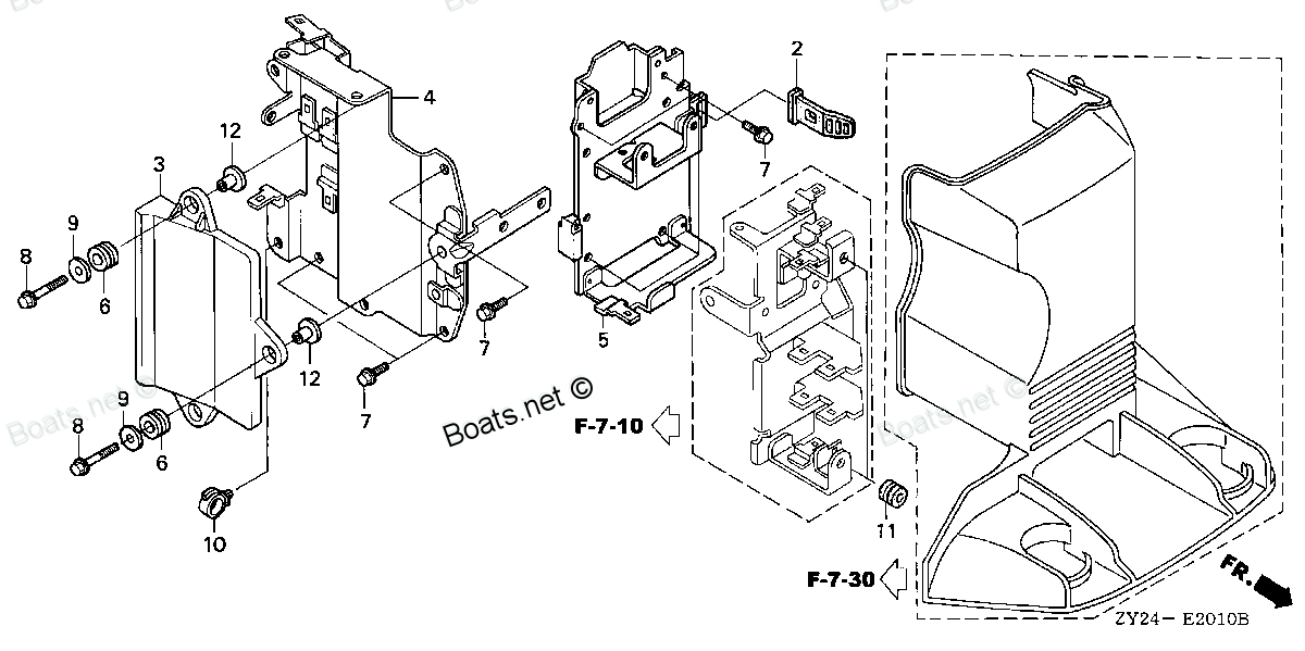
91503-ZY3-000 COLLAR, UNIT (Honda Code 6994685). Honda
BF200A2 LA, BF200A2 XA, BF200A2 XCA, BF200A2 XXA, BF200A2 XXCA, BF200A3 LA, BF200A3 XA, BF200A3 XCA, BF200A3 XXA, BF200A3 XXCA, BF200A4 LA, BF200A4 XA, BF200A4 XCA, BF200A4 XXA, BF200A4 XXCA, BF200A5 LA, BF200A5 XA, BF200A5 XCA, BF200A5 XXA, BF200A5
COLLAR
. Honda parts")
Price: query
Rating:
Number on catalog scheme: 12
Compatible models:
BF200A2 LA
BF200A2 XA
BF200A2 XCA
BF200A2 XXA
BF200A2 XXCA
BF200A3 LA
BF200A3 XA
BF200A3 XCA
BF200A3 XXA
BF200A3 XXCA
BF200A4 LA
BF200A4 XA
BF200A4 XCA
BF200A4 XXA
BF200A4 XXCA
BF200A5 LA
BF200A5 XA
BF200A5 XCA
BF200A5 XXA
BF200A5 XXCA
BF200A6 LA
BF200A6 XA
BF200A6 XCA
BF200A6 XXA
BF200A6 XXCA
BF200AK0 LA
BF200AK0 XA
BF200AK0 XCA
BF225A2 LA
BF225A2 XA
BF225A2 XCA
BF225A2 XXA
BF225A2 XXCA
BF225A3 LA
BF225A3 XA
BF225A3 XCA
BF225A3 XXA
BF225A3 XXCA
BF225A4 LA
BF225A4 XA
BF225A4 XCA
BF225A4 XXA
BF225A4 XXCA
BF225A5 LA
BF225A5 XA
BF225A5 XCA
BF225A5 XXA
BF225A5 XXCA
BF225A6 LA
BF225A6 XA
BF225A6 XCA
BF225A6 XXA
BF225A6 XXCA
BF225AK0 LA
BF225AK0 XA
BF225AK0 XCA
BF225AK0 XXA
BF225AK0 XXCA
Honda
Honda entire parts catalog list:
- ELECTRONIC CONTROL UNIT » 91503-ZY3-000
- ELECTRONIC CONTROL UNIT » 91503-ZY3-000
- ELECTRONIC CONTROL UNIT » 91503-ZY3-000
- ELECTRONIC CONTROL UNIT » 91503-ZY3-000
- ELECTRONIC CONTROL UNIT » 91503-ZY3-000
- ELECTRONIC CONTROL UNIT » 91503-ZY3-000
- ELECTRONIC CONTROL UNIT » 91503-ZY3-000
- ELECTRONIC CONTROL UNIT » 91503-ZY3-000
- ELECTRONIC CONTROL UNIT » 91503-ZY3-000
- ELECTRONIC CONTROL UNIT » 91503-ZY3-000
- ELECTRONIC CONTROL UNIT » 91503-ZY3-000
- ELECTRONIC CONTROL UNIT » 91503-ZY3-000
- ELECTRONIC CONTROL UNIT » 91503-ZY3-000
- ELECTRONIC CONTROL UNIT » 91503-ZY3-000
- ELECTRONIC CONTROL UNIT » 91503-ZY3-000
- ELECTRONIC CONTROL UNIT » 91503-ZY3-000
- ELECTRONIC CONTROL UNIT » 91503-ZY3-000
- ELECTRONIC CONTROL UNIT » 91503-ZY3-000
- ELECTRONIC CONTROL UNIT » 91503-ZY3-000
- ELECTRONIC CONTROL UNIT » 91503-ZY3-000
- ELECTRONIC CONTROL UNIT » 91503-ZY3-000
- ELECTRONIC CONTROL UNIT » 91503-ZY3-000
- ELECTRONIC CONTROL UNIT » 91503-ZY3-000
- ELECTRONIC CONTROL UNIT » 91503-ZY3-000
- ELECTRONIC CONTROL UNIT » 91503-ZY3-000
- ELECTRONIC CONTROL UNIT » 91503-ZY3-000
- ELECTRONIC CONTROL UNIT » 91503-ZY3-000
- ELECTRONIC CONTROL UNIT » 91503-ZY3-000
- ELECTRONIC CONTROL UNIT » 91503-ZY3-000
- ELECTRONIC CONTROL UNIT » 91503-ZY3-000
- ELECTRONIC CONTROL UNIT » 91503-ZY3-000
- ELECTRONIC CONTROL UNIT » 91503-ZY3-000
- ELECTRONIC CONTROL UNIT » 91503-ZY3-000
- ELECTRONIC CONTROL UNIT » 91503-ZY3-000
- ELECTRONIC CONTROL UNIT » 91503-ZY3-000
- ELECTRONIC CONTROL UNIT » 91503-ZY3-000
- ELECTRONIC CONTROL UNIT » 91503-ZY3-000
- ELECTRONIC CONTROL UNIT » 91503-ZY3-000
- ELECTRONIC CONTROL UNIT » 91503-ZY3-000
- ELECTRONIC CONTROL UNIT » 91503-ZY3-000
- ELECTRONIC CONTROL UNIT » 91503-ZY3-000
- ELECTRONIC CONTROL UNIT » 91503-ZY3-000
- ELECTRONIC CONTROL UNIT » 91503-ZY3-000
- ELECTRONIC CONTROL UNIT » 91503-ZY3-000
- ELECTRONIC CONTROL UNIT » 91503-ZY3-000
- ELECTRONIC CONTROL UNIT » 91503-ZY3-000
- ELECTRONIC CONTROL UNIT » 91503-ZY3-000
- ELECTRONIC CONTROL UNIT » 91503-ZY3-000
- ELECTRONIC CONTROL UNIT » 91503-ZY3-000
- ELECTRONIC CONTROL UNIT » 91503-ZY3-000
- ELECTRONIC CONTROL UNIT » 91503-ZY3-000
- ELECTRONIC CONTROL UNIT » 91503-ZY3-000
- ELECTRONIC CONTROL UNIT » 91503-ZY3-000
- ELECTRONIC CONTROL UNIT » 91503-ZY3-000
- ELECTRONIC CONTROL UNIT » 91503-ZY3-000
- ELECTRONIC CONTROL UNIT » 91503-ZY3-000
- ELECTRONIC CONTROL UNIT » 91503-ZY3-000
- ELECTRONIC CONTROL UNIT » 91503-ZY3-000
Information:
Introduction
This Special Instruction describes the basic operation of the Cat® Smart EMS, features, and troubleshooting. Actual screen shots will be used to illustrate specific functions and examples. For information regarding the installation, operation, specifications, and troubleshooting beyond the scope of this manual, see the manuals for the Cat Smart EMS.Do not perform any procedure in this Special Instruction until you have read the information and you understand the information.Important Safety Information
Do not perform any procedure in this Special Instruction until you have read this Special Instruction and you understand this information. Use only proper tools and observe all precautions that pertain to the use of those tools. Failure to follow these procedures can result in personal injury. The following procedures also should be observed.Work safely. Most accidents that involve product operation, maintenance, and repair are caused by failure to observe basic safety rules or precautions. An accident can often be avoided by recognizing potentially hazardous situations before an accident occurs.A person must be alert to potential hazards. This person should also have the necessary training, skills, and tools to perform these functions properly.Safety precautions and warnings are provided in this instruction and on the product. If these hazard warnings are not heeded, bodily injury or death could occur to you or to other persons. Cat cannot anticipate every possible circumstance that might involve a potential hazard.Therefore, the warnings in this publication and the warnings that are on the product are not all inclusive. Ensure that any tool, procedure, work method, or operating technique you use that is not recommended by Cat is safe.Ensure that the product will not be damaged or the product will not be made unsafe by the operation, lubrication, maintenance, or repair procedures used.Ground the equipment. Improper grounding will result in electrical current paths that are uncontrolled and unreliable. Uncontrolled electrical circuit paths can result in damage to the equipment. Uncontrolled electrical circuit paths can also cause electrical activity that may degrade the electronics and communications. Ensure that all grounds are secure and free of corrosion.
Never connect or disconnect the magnet or the generator unless the engine is shut down and the main switch for the generator is in the OFF position.Never handle the leads to the magnet unless the engine is shut down and the main switch at the magnet controller for the generator is in the OFF position.High voltage exists at the generator system when the generator is activated.Failure to follow this procedure may result in personal injury or death.
Accidental engine starting can cause injury or death to personnel.To prevent accidental engine starting, turn the ignition switch to the OFF position and place a do not operate tag at the ignition switch location.
Do not operate or work on this machine unless you have read and understand the instructions and warnings in the Operation and Maintenance Manual. Failure to follow the instructions or heed the warnings could result in injury or death. Contact the Original Equipment Manufacturer (OEM) or representative for replacement manuals. Proper care is your responsibility.
Before starting this installation, in addition to the normal safety precautions taken whereas performing maintenance on heavy machinery, the following lockout/tagout procedure is recommended:
Stop the engine.
Place the disconnect switch in the OFF position.
Illustration 1 g02324673
Place a lockout tag on the disconnect switch.Electrostatic Discharge Awareness
Smart EMS contains components that are sensitive to Electrostatic Discharge (ESD). An electrostatic charge can damage the control resulting in EMCP 4 breakdown or improper operation.Take the following precautions while installing/removing/handling the control:
Handle equipment correctly. Use ESD protective packaging and material handling containers that are antistatic and provide discharge protection and electric field suppression.
Use protective devices: ESD-protective workstations and/or work surfaces (grounding mat, anti-static wrist strap).
Keep all plastic items away from the devices. Any plastic items (candy wrappers, foam cups, synthetic carpet, foam cushions) are a potential static drilling module.
The anti-static bag cannot function as a static dissipating mat.
DO NOT use an anti-static bag for any other purpose than to enclose a product.Note: The 120-pin connector (and a 70-pin connector for EMCP 4.4) on the back of the control is the most vulnerable area to ELECTROSTATIC DISCHARGE (ESD). While handling the EMCP 4, attention is required to the back of the control. The control may become damaged or inoperable if care is not taken.Note: Locking out the drilling module set does not remove voltage on the EMCP 4.4 at the bus voltage sensing leads. Consult the Electrostatic Discharge Association for proper procedure during particular situations .http://www.esda.orgAutomatic Starting and Stopping Awareness
All engines connected to Smart EMS must be in AUTO mode on the EMCP 4.4. When an engine is in AUTO mode, the engine can start at any moment. To avoid personal injury, always remain clear of the engine when the engine is in AUTO mode. Placing an engine in STOP mode does not prevent an engine from automatically starting. Always lock out the starting system prior to servicing the engine.General Information
The Smart EMS is the latest drilling module controller algorithm developed for Land Electric Drilling Rigs. Smart EMS efficiently manages the number of drilling modules required to be online to meet rig power demands throughout the various drilling modes.Smart EMS uses the proven Electronic Modular Control Panel (EMCP 4.4). The EMCP 4.4 is the latest engine and drilling module controller for use on diesel and gas products. The EMCP 4.4 is a scalable control platform suitable for a wide range of applications, from a single module to the paralleling and load sharing of multiple units. The EMCP 4.4 controls engine starting/stopping, and drilling module paralleling functions including automatic and manual synchronizing, main circuit breaker open/close, dead bus arbitration, load sharing, and load sense/load demand. Voltage regulation is provided by connecting the EMCP 4.4 to the Integrated Voltage Regulator (IVR) Module.Smart EMS uses 38 cm (15 inch) Human Machine Interface (HMI) panels provide centralized control of the drilling modules from locations such as the drillers cabin and/or power house.Smart EMS optimizes rig power generation by automatically starting and stopping drilling modules based on overall rig power
Parts collar Honda:
91563-ZV5-000
91563-ZV5-000 COLLAR, DISTANCE (6X10.5X25) (Honda Code 3706900).
BF115A1 LA, BF115A1 LCA, BF115A1 XA, BF115A1 XCA, BF115A2 LA, BF115A2 LCA, BF115A2 XA, BF115A2 XCA, BF115A3 LA, BF115A3 LCA, BF115A3 XA, BF115A3 XCA, BF115A4 LA, BF115A4 LCA, BF115A4 XA, BF115A4 XCA, BF115A5 LA, BF115A5 LCA, BF115A5 XA, BF115A5 XCA,
24854-ZV5-000

24854-ZV5-000 COLLAR, SLIDING PLATE (Honda Code 3703196).
BF115A1 LA, BF115A1 LCA, BF115A1 XA, BF115A1 XCA, BF115A2 LA, BF115A2 LCA, BF115A2 XA, BF115A2 XCA, BF115A3 LA, BF115A3 LCA, BF115A3 XA, BF115A3 XCA, BF115A4 LA, BF115A4 LCA, BF115A4 XA, BF115A4 XCA, BF115A5 LA, BF115A5 LCA, BF115A5 XA, BF115A5 XCA,
91567-ZV5-000
91567-ZV5-000 COLLAR, LINK JOINT (Honda Code 3706918).
BF115A1 LA, BF115A1 LCA, BF115A1 XA, BF115A1 XCA, BF115A2 LA, BF115A2 LCA, BF115A2 XA, BF115A2 XCA, BF115A3 LA, BF115A3 LCA, BF115A3 XA, BF115A3 XCA, BF115A4 LA, BF115A4 LCA, BF115A4 XA, BF115A4 XCA, BF115A5 LA, BF115A5 LCA, BF115A5 XA, BF115A5 XCA,
91570-ZV5-000

91570-ZV5-000 COLLAR, DISTANCE (6X10X43.5) (Honda Code 3706942).
BF115A1 LA, BF115A1 LCA, BF115A1 XA, BF115A1 XCA, BF115A2 LA, BF115A2 LCA, BF115A2 XA, BF115A2 XCA, BF115A3 LA, BF115A3 LCA, BF115A3 XA, BF115A3 XCA, BF115A4 LA, BF115A4 LCA, BF115A4 XA, BF115A4 XCA, BF115A5 LA, BF115A5 LCA, BF115A5 XA, BF115A5 XCA,
91557-ZW1-701
91557-ZW1-701 COLLAR, ORIFICE (Honda Code 5300496).
BF115A1 LA, BF115A1 LCA, BF115A1 XA, BF115A1 XCA, BF115A2 LA, BF115A2 LCA, BF115A2 XA, BF115A2 XCA, BF115A3 LA, BF115A3 LCA, BF115A3 XA, BF115A3 XCA, BF115A4 LA, BF115A4 LCA, BF115A4 XA, BF115A4 XCA, BF115A5 LA, BF115A5 LCA, BF115A5 XA, BF115A5 XCA,
56539-ZW1-000
56539-ZW1-000 COLLAR, CYLINDER (LOWER) (Honda Code 4900288).
BF115A1 LA, BF115A1 LCA, BF115A1 XA, BF115A1 XCA, BF115A2 LA, BF115A2 LCA, BF115A2 XA, BF115A2 XCA, BF115A3 LA, BF115A3 LCA, BF115A3 XA, BF115A3 XCA, BF115A4 LA, BF115A4 LCA, BF115A4 XA, BF115A4 XCA, BF115A5 LA, BF115A5 LCA, BF115A5 XA, BF115A5 XCA,
90511-ZW5-U00
90511-ZW5-U00 COLLAR, DISTANCE (A) (Honda Code 6811178).
BF115A1 LA, BF115A1 LCA, BF115A1 XA, BF115A1 XCA, BF115A2 LA, BF115A2 LCA, BF115A2 XA, BF115A2 XCA, BF115A3 LA, BF115A3 LCA, BF115A3 XA, BF115A3 XCA, BF115A4 LA, BF115A4 LCA, BF115A4 XA, BF115A4 XCA, BF115A5 LA, BF115A5 LCA, BF115A5 XA, BF115A5 XCA,
91560-ZY3-000
91560-ZY3-000 COLLAR, STEERING ROD (Honda Code 6994727).
BF175AK1 LA, BF175AK1 XA, BF175AK1 XCA, BF175AK2 LA, BF175AK2 XA, BF175AK2 XCA, BF200A2 LA, BF200A2 XA, BF200A2 XCA, BF200A2 XXA, BF200A2 XXCA, BF200A3 LA, BF200A3 XA, BF200A3 XCA, BF200A3 XXA, BF200A3 XXCA, BF200A4 LA, BF200A4 XA, BF200A4 XCA, BF200