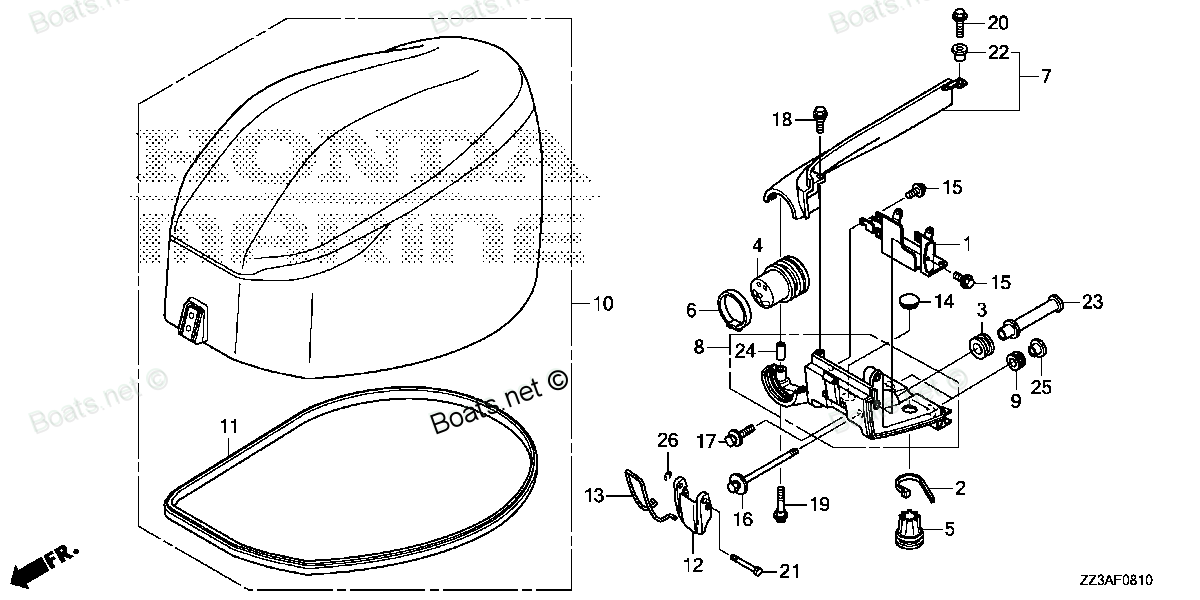
91553-ZY9-000 COLLAR, FR. BRACKET Honda
BF60AK1 LRTA, BF60AK1 XRTA, BF75DK0 LHTA, BF75DK0 LRTA, BF75DK2 LRTA, BF90DK0 LHTA, BF90DK0 LRTA, BF90DK0 XRTA, BF90DK2 LRTA, BF90DK2 XRTA, BFP60AK1 LRTA, BFP60AK1 LRTB, BFP60AK1 XRTA
COLLAR

Price: query
Rating:
Number on catalog scheme: 23
Compatible models:
Honda entire parts catalog list:
- ENGINE COVER » 91553-ZY9-000
- ENGINE COVER » 91553-ZY9-000
- EXTENSION CASE » 91553-ZY9-000
- EXTENSION CASE » 91553-ZY9-000
- EXTENSION CASE » 91553-ZY9-000
- EXTENSION CASE » 91553-ZY9-000
- EXTENSION CASE » 91553-ZY9-000
- EXTENSION CASE » 91553-ZY9-000
- EXTENSION CASE » 91553-ZY9-000
- EXTENSION CASE » 91553-ZY9-000
- ENGINE COVER » 91553-ZY9-000
- ENGINE COVER » 91553-ZY9-000
- ENGINE COVER » 91553-ZY9-000
Information:
Start By:a. remove oil pump1. Check the main bearing caps for identification for their location and direction in the block. The caps must be installed in the same location and direction from which they were removed. 2. Remove number 2 through number 6 bearing caps (1). Remove thrust plates from the number 4 main bearing.
If the crankshaft is turned in the wrong direction, the tab of the bearing will be pushed between the crankshaft and cylinder block. This can cause damage to either the crankshaft or cylinder block or both.
3. Remove the upper halves of the main bearings by putting Tool (A) in oil hole (2) in the crankshaft. Turn the crankshaft in the direction which will push the end of the bearing with a tab out first.4. Remove the lower halves of the bearings from the caps. Install the bearings dry when the clearance checks are made. Put clean engine oil on the bearings for final assembly.5. Install the new bearings in the caps.6. Install the upper halves of the bearings in the cylinder block with Tool (A).
Be sure tabs (3) on the back of the bearings fit in the tab slots of the caps and cylinder block. The serviceman must be very careful to use Plastigage, Tool (B) correctly. The following points must be remembered.
... Make sure that the backs of the bearings and the bores are clean and dry.... Make sure that the bearing locking tabs are properly seated in their slots.... The crankshaft must be free of oil where the Plastigage touches it.... If the main bearing clearances are checked with the engine upright or on its side, the crankshaft must be supported. Use a jack under an adjacent crankshaft counter weight and hold the crankshaft against the crown of the bearing. If the crankshaft is not supported, the weight of the crankshaft will cause incorrect readings.... Put a piece of Plastigage on the crown of the bearing half that is in the cap. Do not allow the Plastigage to extend over the edge of the bearing.... Install the bearing cap using the correct torque-turn specifications. Do not use an impact wrench. Be careful not to dislodge the bearing when the cap is installed.... Do not turn the crankshaft with the Plastigage installed. ... Carefully remove the cap but do not remove the Plastigage. Measure the width of the Plastigage while it is in the bearing cap or on the crankshaft journal. Do this by using the correct scale on the package. Record the measurements.... Remove the Plastigage before reinstating the cap. When using Plastigage, the readings can sometimes be unclear. For example, all parts of the Plastigage are not the same width. Measure the major widths to make sure that they are within the specification range. Also, experience has shown that when checking clearances tighter than 0.10 mm (.004 in)the readings maybe low by 0.013 to 0.025 mm (.0005 to .0010 in).Out-of-round journals can give faulty readings. Also, journal taper may be indicated when one end of the Plastigage is wider than the other.For complete details concerning measuring bearing clearances, see Engine Bearings & Crankshafts, SEBD0531.7. Check the bearing clearance with Plastigage (B). Put Plastigage (B) on the bearings.
Typical Example
Do not use an impact wrench to tighten the bolts the additional 120 5 degreesof a turn more.
Be sure the main bearing caps are installed so the numbers on the side of the cylinder block are the same as the numbers on the bearing camps, and the arrows (4) on the bearing caps are toward the front of the cylinder block.
8. Install the bearing caps for No. 2 through No. 6 main bearings. Put 2P-2506 Thread Lubricanton the bolts. Install the bolts, and tighten bolts at end with tab first to a torque of 260 14 N m (190 10 lb ft).Turn the bolts an extra 120 5 degreesfirst at the end opposite of the tab. Remove the bearing caps for No. 2 through No. 6 main bearings. Remove Plastigage (B) from the caps. Check the thickness of Plastigage (B) to find the bearing clearance. The bearing clearance must be 0.091 to 0.185 mm (.0036 to .0073 in)with new bearings. Maximum clearance with used bearings is 0.25 mm (.010 in).9. Put 2P-2506 Thread Lubricanton the threads of the bolts. Install the bearing caps for No. 2 through No. 6 main bearings. Install the bolts, and tighten the bolts at the end with the tab first to a torque of 260 14 N m (190 10 lb ft).Put a mark on the bolts and caps. Turn the bolts at the opposite end of the tab first an extra 120 5 degreesfrom the mark.10. Remove the No. 1 and No. 7 main bearing caps. Do Steps 3 through 9 for the No. 1 and No. 7 caps.11. Install the thrust plates for No. 4 main bearing. Install the thrust plates with the identification "BLOCK SIDE" toward the cylinder block.12. Check the end play of the crankshaft with Tool (C). Be sure the dial indicator is against a machined surface. The end play is controlled by the thrust plates of No. 4 (center) main bearing. The end play with new thrust plates must be 0.15 to .051 mm (.006 to .020 in).The maximum permissible end play used thrust plates is 0.89 mm (.035 in).End By:a. install oil pump
Parts collar Honda:
91556-ZV5-000
91556-ZV5-000 COLLAR, DISTANCE (10X90) (Honda Code 3706876).
BF35AM LHA, BF35AM LRA, BF35AM LRTA, BF35AM SHA, BF35AM XRTA, BF40A1 LHA, BF40A1 LHTA, BF40A1 LRA, BF40A1 LRTA, BF40A1 XRTA, BF40A2 LHA, BF40A2 LHTA, BF40A2 LRA, BF40A2 LRTA, BF40A2 XRTA, BF40A3 LHA, BF40A3 LHTA, BF40A3 LRA, BF40A3 LRTA, BF40A3 XRTA,
24854-ZV5-000

24854-ZV5-000 COLLAR, SLIDING PLATE (Honda Code 3703196).
BF115A1 LA, BF115A1 LCA, BF115A1 XA, BF115A1 XCA, BF115A2 LA, BF115A2 LCA, BF115A2 XA, BF115A2 XCA, BF115A3 LA, BF115A3 LCA, BF115A3 XA, BF115A3 XCA, BF115A4 LA, BF115A4 LCA, BF115A4 XA, BF115A4 XCA, BF115A5 LA, BF115A5 LCA, BF115A5 XA, BF115A5 XCA,
91567-ZV5-000
91567-ZV5-000 COLLAR, LINK JOINT (Honda Code 3706918).
BF115A1 LA, BF115A1 LCA, BF115A1 XA, BF115A1 XCA, BF115A2 LA, BF115A2 LCA, BF115A2 XA, BF115A2 XCA, BF115A3 LA, BF115A3 LCA, BF115A3 XA, BF115A3 XCA, BF115A4 LA, BF115A4 LCA, BF115A4 XA, BF115A4 XCA, BF115A5 LA, BF115A5 LCA, BF115A5 XA, BF115A5 XCA,
91570-ZV5-000

91570-ZV5-000 COLLAR, DISTANCE (6X10X43.5) (Honda Code 3706942).
BF115A1 LA, BF115A1 LCA, BF115A1 XA, BF115A1 XCA, BF115A2 LA, BF115A2 LCA, BF115A2 XA, BF115A2 XCA, BF115A3 LA, BF115A3 LCA, BF115A3 XA, BF115A3 XCA, BF115A4 LA, BF115A4 LCA, BF115A4 XA, BF115A4 XCA, BF115A5 LA, BF115A5 LCA, BF115A5 XA, BF115A5 XCA,
91560-ZV5-000
91560-ZV5-000 COLLAR, STEERING ROD (Honda Code 3706892).
BF115A1 LA, BF115A1 LCA, BF115A1 XA, BF115A1 XCA, BF115A2 LA, BF115A2 LCA, BF115A2 XA, BF115A2 XCA, BF115A3 LA, BF115A3 LCA, BF115A3 XA, BF115A3 XCA, BF115A4 LA, BF115A4 LCA, BF115A4 XA, BF115A4 XCA, BF115A5 LA, BF115A5 LCA, BF115A5 XA, BF115A5 XCA,
91553-ZZ3-000
91553-ZZ3-000 COLLAR, DISTANCE (6.1X9.1X20.5)
BF60AK1 LRTA, BF60AK1 XRTA, BFP60AK1 LRTA, BFP60AK1 LRTB, BFP60AK1 XRTA
91555-ZZ3-000
91555-ZZ3-000 COLLAR, DISTANCE (6.5X16X14.5)
BF60AK1 LRTA, BF60AK1 XRTA, BFP60AK1 LRTA, BFP60AK1 LRTB, BFP60AK1 XRTA
91552-ZZ3-000