17275-ZW5-000 COVER, BREATHER ELEMENT (Honda Code 5971593). Honda
BF115A1 LA, BF115A1 LCA, BF115A1 XA, BF115A1 XCA, BF115A2 LA, BF115A2 LCA, BF115A2 XA, BF115A2 XCA, BF115A3 LA, BF115A3 LCA, BF115A3 XA, BF115A3 XCA, BF115A4 LA, BF115A4 LCA, BF115A4 XA, BF115A4 XCA, BF115A5 LA, BF115A5 LCA, BF115A5 XA, BF115A5 XCA,
COVER
. Honda parts")
Price: query
Rating:
Number on catalog scheme: 8
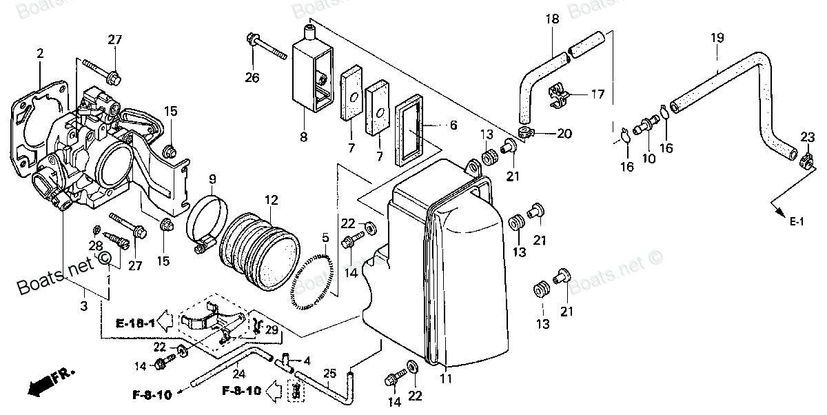
Compatible models:
BF115A1 LA
BF115A1 LCA
BF115A1 XA
BF115A1 XCA
BF115A2 LA
BF115A2 LCA
BF115A2 XA
BF115A2 XCA
BF115A3 LA
BF115A3 LCA
BF115A3 XA
BF115A3 XCA
BF115A4 LA
BF115A4 LCA
BF115A4 XA
BF115A4 XCA
BF115A5 LA
BF115A5 LCA
BF115A5 XA
BF115A5 XCA
BF115A6 LA
BF115A6 LCA
BF115A6 XA
BF115A6 XCA
BF115AK0 LA
BF115AK0 XA
BF115AX LA
BF115AX LCA
BF115AX XA
BF115AX XCA
BF115AY LA
BF115AY LCA
BF115AY XA
BF115AY XCA
BF130A1 LA
BF130A1 LCA
BF130A1 XA
BF130A1 XCA
BF130A2 LA
BF130A2 LCA
BF130A2 XA
BF130A2 XCA
BF130A3 LA
BF130A3 LCA
BF130A3 XA
BF130A3 XCA
BF130A4 LA
BF130A4 LCA
BF130A4 XA
BF130A4 XCA
BF130AX LA
BF130AX LCA
BF130AX XA
BF130AX XCA
BF130AY LA
BF130AY LCA
BF130AY XA
BF130AY XCA
Honda
Honda entire parts catalog list:
- THROTTLE BODY » 17275-ZW5-000
- THROTTLE BODY » 17275-ZW5-000
- THROTTLE BODY » 17275-ZW5-000
- THROTTLE BODY » 17275-ZW5-000
- THROTTLE BODY » 17275-ZW5-000
- THROTTLE BODY » 17275-ZW5-000
- THROTTLE BODY » 17275-ZW5-000
- THROTTLE BODY » 17275-ZW5-000
- THROTTLE BODY » 17275-ZW5-000
- THROTTLE BODY » 17275-ZW5-000
- THROTTLE BODY » 17275-ZW5-000
- THROTTLE BODY » 17275-ZW5-000
- THROTTLE BODY » 17275-ZW5-000
- THROTTLE BODY » 17275-ZW5-000
- THROTTLE BODY » 17275-ZW5-000
- THROTTLE BODY » 17275-ZW5-000
- THROTTLE BODY » 17275-ZW5-000
- THROTTLE BODY » 17275-ZW5-000
- THROTTLE BODY » 17275-ZW5-000
- THROTTLE BODY » 17275-ZW5-000
- THROTTLE BODY » 17275-ZW5-000
- THROTTLE BODY » 17275-ZW5-000
- THROTTLE BODY » 17275-ZW5-000
- THROTTLE BODY » 17275-ZW5-000
- THROTTLE BODY » 17275-ZW5-000
- THROTTLE BODY » 17275-ZW5-000
- THROTTLE BODY » 17275-ZW5-000
- THROTTLE BODY » 17275-ZW5-000
- THROTTLE BODY » 17275-ZW5-000
- THROTTLE BODY » 17275-ZW5-000
- THROTTLE BODY » 17275-ZW5-000
- THROTTLE BODY » 17275-ZW5-000
- THROTTLE BODY » 17275-ZW5-000
- THROTTLE BODY » 17275-ZW5-000
- THROTTLE BODY » 17275-ZW5-000
- THROTTLE BODY » 17275-ZW5-000
- THROTTLE BODY » 17275-ZW5-000
- THROTTLE BODY » 17275-ZW5-000
- THROTTLE BODY » 17275-ZW5-000
- THROTTLE BODY » 17275-ZW5-000
- THROTTLE BODY » 17275-ZW5-000
- THROTTLE BODY » 17275-ZW5-000
- THROTTLE BODY » 17275-ZW5-000
- THROTTLE BODY » 17275-ZW5-000
- THROTTLE BODY » 17275-ZW5-000
- THROTTLE BODY » 17275-ZW5-000
- THROTTLE BODY » 17275-ZW5-000
- THROTTLE BODY » 17275-ZW5-000
- THROTTLE BODY » 17275-ZW5-000
- THROTTLE BODY » 17275-ZW5-000
- THROTTLE BODY » 17275-ZW5-000
- THROTTLE BODY » 17275-ZW5-000
- THROTTLE BODY » 17275-ZW5-000
- THROTTLE BODY » 17275-ZW5-000
- THROTTLE BODY » 17275-ZW5-000
- THROTTLE BODY » 17275-ZW5-000
- THROTTLE BODY » 17275-ZW5-000
- THROTTLE BODY » 17275-ZW5-000
Information:
Visual Inspection
Inspect the following parts at each oil change:
Air lines
Hoses
Gasket joints
Pressurized air can cause personal injury. When pressurized air is used for cleaning, wear a protective face shield, protective clothing, and protective shoes.
Ensure that the constant torque hose clamps are tightened to the correct torque. Refer to Torque Specifications, SENR3130, "Standard Torque for Constant Torque Hose Clamps" for the correct torque. Check the welded joints for cracks. Ensure that the brackets are tightened in the correct positions. Ensure that the brackets are in good condition. Use compressed air to clean any debris or any dust from the aftercooler core assembly. Inspect the fins of the aftercooler for the following conditions:
Damage
Debris
CorrosionUse a stainless steel brush to remove any corrosion.Note: When parts of the aftercooler system are repaired or replaced, a leak test is recommended.Inlet Manifold Pressure
Normal inlet manifold pressure with high exhaust temperature can be caused by blockage of the aftercooler core. Clean the aftercooler core.Low inlet manifold pressure and high exhaust manifold temperature can be caused by any of the following conditions:Plugged air cleaner - Clean the air cleaner or replace the air cleaner, as required. Refer to the Operation and Maintenance Manual, "Engine Air Cleaner Element (Dual Element) - Clean/Replace".Blockage in the air lines - Blockage in the air lines between the air cleaner and the turbocharger must be removed.Inlet manifold leak - An inlet manifold leak can be caused by the following conditions: loose fittings and plugs, missing fittings and plugs, damaged fittings and plugs and leaking inlet manifold gasket.Air System Restriction
Pressure measurements should be taken at the inlet manifold and at the turbocharger outlet.Use the differential pressure gauge of the 1U-5470 Engine Pressure Group or use the 198-4240 Digital Pressure Indicator. Use the following procedure in order to measure the restriction of the aftercooler:
Connect the vacuum port of the differential pressure gauge to port (10).
Connect the pressure port of the differential pressure gauge to port (11).
Record the value. The air lines and the cooler core must be inspected for internal restriction when both of the following conditions are met:
Air flow is at a maximum level.
Total air pressure drop of the charged system exceeds 16.9 kPa (5 in Hg).If a restriction is discovered, proceed with the following tasks, as required:
Clean
Repair
ReplacementLeak Test for the Sea Water Cooling System
Test for Water Leaks
Remove the aftercooler core from the engine. Refer to Disassembly and Assembly, "Aftercooler and Aftercooler Core".
Thoroughly clean the aftercooler core.
Plug the fittings of the aftercooler core.
Pressurize the aftercooler core to 240 kPa (35 psi).
Spray the aftercooler core with a mixture of water and a soap solution. Look for air bubbles that form on the aftercooler core. Test for Air Leaks
The bottom opening of the aftercooler must be closed in order to perform the following pressure test. A cover may need to be fabricated in order to plug the opening.
Remove the aftercooler from the engine. Refer to Disassembly and Assembly, "Aftercooler and Aftercooler Core".
Assemble the aftercooler on the bench. Refer to Disassembly and Assembly, "Aftercooler and Aftercooler Core".
Plug the openings of the aftercooler and pressurize the aftercooler to 205 kPa (30 psi).
Spray the aftercooler core with a mixture of water and a soap solution. Look for air bubbles that form on the aftercooler core. Turbocharger Failure
Personal injury can result from air pressure.Personal injury can result without following proper procedure. When using pressure air, wear a protective face shield and protective clothing.Maximum air pressure at the nozzle must be less than 205 kPa (30 psi) for cleaning purposes.
If a turbocharger failure occurs, remove the aftercooler core. Internally flush the aftercooler core with a solvent that removes oil and other foreign substances. Wash the aftercooler with hot, soapy water. Thoroughly rinse the aftercooler with clean water and blow dry the aftercooler with compressed air. Blow dry the assembly in the reverse direction of normal air flow. To make sure that the whole system is clean, carefully inspect the system.Dynamometer Test
In hot ambient temperatures, dynamometer tests for models with an aftercooler can add a greater heat load to the jacket water cooling system. Therefore, the jacket water cooling systems temperature must be monitored. The following measurements may also need a power correction factor:
Inlet air temperature
Fuel API rating
Fuel temperature
Barometric pressureWith dynamometer tests for engines, use the FT-1438 Aftercooler Gp (DYNAMOMETER TEST). This tool provides a water-cooled aftercooler in order to control the inlet air temperature to 43 °C (110 °F).
Parts cover Honda:
38216-ZV5-003

38216-ZV5-003 COVER ASSY., FUSE (15A) (Honda Code 8449142).
BF25D4 LHTA, BF25D4 LRGA, BF25D4 LRTA, BF25D4 SHGA, BF25D4 SRGA, BF25D4 SRTA, BF25D5 LHTA, BF25D5 LRGA, BF25D5 LRTA, BF25D5 SHGA, BF25D5 SRGA, BF25D5 SRTA, BF25D6 LHTA, BF25D6 LRGA, BF25D6 LRTA, BF25D6 SHGA, BF25D6 SRGA, BF25D6 SRTA, BF25DK0 LRGA, BF
38216-ZW1-003

38216-ZW1-003 COVER ASSY., FUSE (30A) (Honda Code 8449159).
BF115A3 LA, BF115A3 LCA, BF115A3 XA, BF115A3 XCA, BF115A4 LA, BF115A4 LCA, BF115A4 XA, BF115A4 XCA, BF115A5 LA, BF115A5 LCA, BF115A5 XA, BF115A5 XCA, BF115A6 LA, BF115A6 LCA, BF115A6 XA, BF115A6 XCA, BF115AK0 LA, BF115AK0 XA, BF130A3 LA, BF130A3 LCA,
24812-ZW7-U01
24812-ZW7-U01 COVER, GRIP (Honda Code 6799548).
BF115A1 LA, BF115A1 LCA, BF115A1 XA, BF115A1 XCA, BF115A2 LA, BF115A2 LCA, BF115A2 XA, BF115A2 XCA, BF115A3 LA, BF115A3 LCA, BF115A3 XA, BF115A3 XCA, BF115A4 LA, BF115A4 LCA, BF115A4 XA, BF115A4 XCA, BF115A5 LA, BF115A5 LCA, BF115A5 XA, BF115A5 XCA,
24814-ZW7-U01
24814-ZW7-U01 COVER, LOCK ARM (Honda Code 6799597).
BF115A1 LA, BF115A1 LCA, BF115A1 XA, BF115A1 XCA, BF115A2 LA, BF115A2 LCA, BF115A2 XA, BF115A2 XCA, BF115A3 LA, BF115A3 LCA, BF115A3 XA, BF115A3 XCA, BF115A4 LA, BF115A4 LCA, BF115A4 XA, BF115A4 XCA, BF115A5 LA, BF115A5 LCA, BF115A5 XA, BF115A5 XCA,
24812-ZW5-U01
24812-ZW5-U01 COVER, L. GRIP (Honda Code 6799522).
BF115A1 LA, BF115A1 LCA, BF115A1 XA, BF115A1 XCA, BF115A2 LA, BF115A2 LCA, BF115A2 XA, BF115A2 XCA, BF115A3 LA, BF115A3 LCA, BF115A3 XA, BF115A3 XCA, BF115A4 LA, BF115A4 LCA, BF115A4 XA, BF115A4 XCA, BF115A5 LA, BF115A5 LCA, BF115A5 XA, BF115A5 XCA,
24813-ZW5-U21
24813-ZW5-U21 COVER, DUAL GRIP (Honda Code 6799563).
BF115A1 LA, BF115A1 LCA, BF115A1 XA, BF115A1 XCA, BF115A2 LA, BF115A2 LCA, BF115A2 XA, BF115A2 XCA, BF115A3 LA, BF115A3 LCA, BF115A3 XA, BF115A3 XCA, BF115A4 LA, BF115A4 LCA, BF115A4 XA, BF115A4 XCA, BF115A5 LA, BF115A5 LCA, BF115A5 XA, BF115A5 XCA,
24812-ZW5-U11
24812-ZW5-U11 COVER, R. GRIP (Honda Code 6799530).
BF115A1 LA, BF115A1 LCA, BF115A1 XA, BF115A1 XCA, BF115A2 LA, BF115A2 LCA, BF115A2 XA, BF115A2 XCA, BF115A3 LA, BF115A3 LCA, BF115A3 XA, BF115A3 XCA, BF115A4 LA, BF115A4 LCA, BF115A4 XA, BF115A4 XCA, BF115A5 LA, BF115A5 LCA, BF115A5 XA, BF115A5 XCA,
31138-PD1-004
31138-PD1-004 COVER, BEARING (Honda Code 1565803).
BF115A1 LA, BF115A1 LCA, BF115A1 XA, BF115A1 XCA, BF115A2 LA, BF115A2 LCA, BF115A2 XA, BF115A2 XCA, BF115A3 LA, BF115A3 LCA, BF115A3 XA, BF115A3 XCA, BF115A4 LA, BF115A4 LCA, BF115A4 XA, BF115A4 XCA, BF115A5 LA, BF115A5 LCA, BF115A5 XA, BF115A5 XCA,