19295-ZW5-000ZA COVER, RELIEF VALVE *NH8* (Honda Code 5891403). (DARK GRAY) Honda
BF115A1 LA, BF115A1 LCA, BF115A1 XA, BF115A1 XCA, BF115A2 LA, BF115A2 LCA, BF115A2 XA, BF115A2 XCA, BF115A3 LA, BF115A3 LCA, BF115A3 XA, BF115A3 XCA, BF115A4 LA, BF115A4 LCA, BF115A4 XA, BF115A4 XCA, BF115A5 LA, BF115A5 LCA, BF115A5 XA, BF115A5 XCA,
COVER
. (DARK GRAY) Honda parts")
Price: query
Rating:
Number on catalog scheme: 3
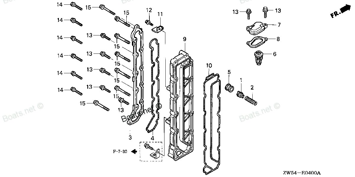
Compatible models:
BF115A1 LA
BF115A1 LCA
BF115A1 XA
BF115A1 XCA
BF115A2 LA
BF115A2 LCA
BF115A2 XA
BF115A2 XCA
BF115A3 LA
BF115A3 LCA
BF115A3 XA
BF115A3 XCA
BF115A4 LA
BF115A4 LCA
BF115A4 XA
BF115A4 XCA
BF115A5 LA
BF115A5 LCA
BF115A5 XA
BF115A5 XCA
BF115A6 LA
BF115A6 LCA
BF115A6 XA
BF115A6 XCA
BF115AK0 LA
BF115AK0 XA
BF115AX LA
BF115AX LCA
BF115AX XA
BF115AX XCA
BF115AY LA
BF115AY LCA
BF115AY XA
BF115AY XCA
BF130A1 LA
BF130A1 LCA
BF130A1 XA
BF130A1 XCA
BF130A2 LA
BF130A2 LCA
BF130A2 XA
BF130A2 XCA
BF130A3 LA
BF130A3 LCA
BF130A3 XA
BF130A3 XCA
BF130A4 LA
BF130A4 LCA
BF130A4 XA
BF130A4 XCA
BF130AX LA
BF130AX LCA
BF130AX XA
BF130AX XCA
BF130AY LA
BF130AY LCA
BF130AY XA
BF130AY XCA
Honda
Honda entire parts catalog list:
- THERMOSTAT » 19295-ZW5-000ZA
- THERMOSTAT » 19295-ZW5-000ZA
- THERMOSTAT » 19295-ZW5-000ZA
- THERMOSTAT » 19295-ZW5-000ZA
- THERMOSTAT » 19295-ZW5-000ZA
- THERMOSTAT » 19295-ZW5-000ZA
- THERMOSTAT » 19295-ZW5-000ZA
- THERMOSTAT » 19295-ZW5-000ZA
- THERMOSTAT » 19295-ZW5-000ZA
- THERMOSTAT » 19295-ZW5-000ZA
- THERMOSTAT » 19295-ZW5-000ZA
- THERMOSTAT » 19295-ZW5-000ZA
- THERMOSTAT » 19295-ZW5-000ZA
- THERMOSTAT » 19295-ZW5-000ZA
- THERMOSTAT » 19295-ZW5-000ZA
- THERMOSTAT » 19295-ZW5-000ZA
- THERMOSTAT » 19295-ZW5-000ZA
- THERMOSTAT » 19295-ZW5-000ZA
- THERMOSTAT » 19295-ZW5-000ZA
- THERMOSTAT » 19295-ZW5-000ZA
- THERMOSTAT » 19295-ZW5-000ZA
- THERMOSTAT » 19295-ZW5-000ZA
- THERMOSTAT » 19295-ZW5-000ZA
- THERMOSTAT » 19295-ZW5-000ZA
- THERMOSTAT » 19295-ZW5-000ZA
- THERMOSTAT » 19295-ZW5-000ZA
- THERMOSTAT » 19295-ZW5-000ZA
- THERMOSTAT » 19295-ZW5-000ZA
- THERMOSTAT » 19295-ZW5-000ZA
- THERMOSTAT » 19295-ZW5-000ZA
- THERMOSTAT » 19295-ZW5-000ZA
- THERMOSTAT » 19295-ZW5-000ZA
- THERMOSTAT » 19295-ZW5-000ZA
- THERMOSTAT » 19295-ZW5-000ZA
- THERMOSTAT » 19295-ZW5-000ZA
- THERMOSTAT » 19295-ZW5-000ZA
- THERMOSTAT » 19295-ZW5-000ZA
- THERMOSTAT » 19295-ZW5-000ZA
- THERMOSTAT » 19295-ZW5-000ZA
- THERMOSTAT » 19295-ZW5-000ZA
- THERMOSTAT » 19295-ZW5-000ZA
- THERMOSTAT » 19295-ZW5-000ZA
- THERMOSTAT » 19295-ZW5-000ZA
- THERMOSTAT » 19295-ZW5-000ZA
- THERMOSTAT » 19295-ZW5-000ZA
- THERMOSTAT » 19295-ZW5-000ZA
- THERMOSTAT » 19295-ZW5-000ZA
- THERMOSTAT » 19295-ZW5-000ZA
- THERMOSTAT » 19295-ZW5-000ZA
- THERMOSTAT » 19295-ZW5-000ZA
- THERMOSTAT » 19295-ZW5-000ZA
- THERMOSTAT » 19295-ZW5-000ZA
- THERMOSTAT » 19295-ZW5-000ZA
- THERMOSTAT » 19295-ZW5-000ZA
- THERMOSTAT » 19295-ZW5-000ZA
- THERMOSTAT » 19295-ZW5-000ZA
- THERMOSTAT » 19295-ZW5-000ZA
- THERMOSTAT » 19295-ZW5-000ZA
Information:
Table 1
Diagnostic Trouble Codes for Ether Injection
J1939 Code Code Description Comments
626-5 Ether Injection Control Solenoid : Current Below Normal The Electronic Control Module (ECM) detects the following conditions:
A low current condition in the output from the ECM to the solenoid for ether injection
The ECM has been powered for at least 2 seconds.
If equipped, the warning lamp will come on. The ECM will log the diagnostic code.
626-6 Ether Injection Control Solenoid : Current Above Normal The Electronic Control Module (ECM) detects the following conditions:
A high current condition in the output from the ECM to the solenoid for ether injection
The ECM has been powered for at least 2 seconds.
If equipped, the warning lamp will come on. The ECM will log the diagnostic code. If there is an active engine shutdown, the ether injection system is disabled . The ether system will be disabled if the glow plugs have been activated in the last 5 minutes.Activation of the ether starting aid is based on the minimum temperature from one of the following temperature sensors:
Intake manifold temperature sensor
Air intake temperature sensor
Coolant temperature sensorRefer to Illustration 1.
Illustration 1 g06396017The following conditions must be met for the ether injection system to be enabled:
Ether injection is set to "Enabled" in the ECM parameters
The lower of the intake manifold air temperature, the air inlet temperature, or the coolant temperature is less than the activation point for ether start aid. Refer to Illustration 1.
The maximum temperature of the intake manifold air temperature sensor, the air inlet temperature sensor, or the coolant temperature sensor is below 50° C (122° F).During the following procedure, refer to the electrical schematic for the application.Complete the procedure in the order in which the steps are listed.
Table 2
Troubleshooting Test Steps Values Results
1. Inspect Electrical Connectors and Wiring
A. Remove the electrical power from the ECM.
B. Thoroughly inspect the connector for the ether injection solenoid. Refer to Troubleshooting, "Electrical Connectors - Inspect".
C. Perform a 30 N (6.7 lb) pull test on each of the wires in the ether solenoid connector.
D. Check the harness and the wiring for abrasion and for pinch points.
Note: Do not disconnect the ECM connector at this stage. The ECM can only be disconnected and reconnected 10 times before damage to the harness connector may occur.
Loose connection or damaged wire
Result: The harness and wiring are OK.
Proceed to Test Step 2.
Result: There is a fault in a connector or the wiring.
Repair: Repair any faulty connectors or replace the wiring harness. Ensure that all the seals are properly in place and ensure that the connectors are correctly coupled.
Proceed to Test Step 4.
2. Check the Wiring Between the ECM and the Ether Control
The ether canister must be removed prior to performing this procedure.
A. Verify that the keyswitch is in the OFF position.
B. Remove the ether canister.
C. Disconnect the engine harness connector for the ether control.
D. Connect a digital voltmeter across the two terminals on the engine harness connector for ether control.
E. Turn the keyswitch to the ON position.
F. Measure the voltage across the terminals while the keyswitch is turned ON.
10 VDC
Result: The voltage measured 0 VDC.
Repair: There is a problem in an electrical component between the ECM and the harness connector for the ether control. The problem may be inside an electrical connector. Make the necessary repairs.
Proceed to Test Step 3.
Result: The voltage measured greater than 10 VDC.
The electrical components between the ECM and the harness connector for the ether control are OK.
Proceed to Test Step 3.
3. Measure the Resistance of the Coil Inside the Ether Control
A. Verify that the ether control is not connected to the engine harness.
B. Measure the resistance of the coil inside the ether control.
20 Ohms
Result: The measured resistance was approximately 20 Ohms.
Proceed to Test Step 4.
Result: The measured resistance was not approximately 20 Ohms.
Repair: Replace the ether control.
Proceed to Test Step 4.
Illustration 2 g03152796
Ether solenoid activation pin
Table 3
Troubleshooting Test Steps Values Results
4. Verify the Repair
A. Activate the Ether Injection Override.
B. Verify that the plunger moved up when the override was active.
Plunger movement
Result: The plunger moved up when the override was active.
Install the ether bottle and return the unit to service.
If the procedure did not correct the issue, contact the Dealer Solutions Network (DSN).
Parts cover Honda:
38216-ZV5-003

38216-ZV5-003 COVER ASSY., FUSE (15A) (Honda Code 8449142).
BF25D4 LHTA, BF25D4 LRGA, BF25D4 LRTA, BF25D4 SHGA, BF25D4 SRGA, BF25D4 SRTA, BF25D5 LHTA, BF25D5 LRGA, BF25D5 LRTA, BF25D5 SHGA, BF25D5 SRGA, BF25D5 SRTA, BF25D6 LHTA, BF25D6 LRGA, BF25D6 LRTA, BF25D6 SHGA, BF25D6 SRGA, BF25D6 SRTA, BF25DK0 LRGA, BF
38216-ZW1-003

38216-ZW1-003 COVER ASSY., FUSE (30A) (Honda Code 8449159).
BF115A3 LA, BF115A3 LCA, BF115A3 XA, BF115A3 XCA, BF115A4 LA, BF115A4 LCA, BF115A4 XA, BF115A4 XCA, BF115A5 LA, BF115A5 LCA, BF115A5 XA, BF115A5 XCA, BF115A6 LA, BF115A6 LCA, BF115A6 XA, BF115A6 XCA, BF115AK0 LA, BF115AK0 XA, BF130A3 LA, BF130A3 LCA,
24812-ZW7-U01
24812-ZW7-U01 COVER, GRIP (Honda Code 6799548).
BF115A1 LA, BF115A1 LCA, BF115A1 XA, BF115A1 XCA, BF115A2 LA, BF115A2 LCA, BF115A2 XA, BF115A2 XCA, BF115A3 LA, BF115A3 LCA, BF115A3 XA, BF115A3 XCA, BF115A4 LA, BF115A4 LCA, BF115A4 XA, BF115A4 XCA, BF115A5 LA, BF115A5 LCA, BF115A5 XA, BF115A5 XCA,
24814-ZW7-U01
24814-ZW7-U01 COVER, LOCK ARM (Honda Code 6799597).
BF115A1 LA, BF115A1 LCA, BF115A1 XA, BF115A1 XCA, BF115A2 LA, BF115A2 LCA, BF115A2 XA, BF115A2 XCA, BF115A3 LA, BF115A3 LCA, BF115A3 XA, BF115A3 XCA, BF115A4 LA, BF115A4 LCA, BF115A4 XA, BF115A4 XCA, BF115A5 LA, BF115A5 LCA, BF115A5 XA, BF115A5 XCA,
24812-ZW5-U01
24812-ZW5-U01 COVER, L. GRIP (Honda Code 6799522).
BF115A1 LA, BF115A1 LCA, BF115A1 XA, BF115A1 XCA, BF115A2 LA, BF115A2 LCA, BF115A2 XA, BF115A2 XCA, BF115A3 LA, BF115A3 LCA, BF115A3 XA, BF115A3 XCA, BF115A4 LA, BF115A4 LCA, BF115A4 XA, BF115A4 XCA, BF115A5 LA, BF115A5 LCA, BF115A5 XA, BF115A5 XCA,
24813-ZW5-U21
24813-ZW5-U21 COVER, DUAL GRIP (Honda Code 6799563).
BF115A1 LA, BF115A1 LCA, BF115A1 XA, BF115A1 XCA, BF115A2 LA, BF115A2 LCA, BF115A2 XA, BF115A2 XCA, BF115A3 LA, BF115A3 LCA, BF115A3 XA, BF115A3 XCA, BF115A4 LA, BF115A4 LCA, BF115A4 XA, BF115A4 XCA, BF115A5 LA, BF115A5 LCA, BF115A5 XA, BF115A5 XCA,
24812-ZW5-U11
24812-ZW5-U11 COVER, R. GRIP (Honda Code 6799530).
BF115A1 LA, BF115A1 LCA, BF115A1 XA, BF115A1 XCA, BF115A2 LA, BF115A2 LCA, BF115A2 XA, BF115A2 XCA, BF115A3 LA, BF115A3 LCA, BF115A3 XA, BF115A3 XCA, BF115A4 LA, BF115A4 LCA, BF115A4 XA, BF115A4 XCA, BF115A5 LA, BF115A5 LCA, BF115A5 XA, BF115A5 XCA,
31138-PD1-004
31138-PD1-004 COVER, BEARING (Honda Code 1565803).
BF115A1 LA, BF115A1 LCA, BF115A1 XA, BF115A1 XCA, BF115A2 LA, BF115A2 LCA, BF115A2 XA, BF115A2 XCA, BF115A3 LA, BF115A3 LCA, BF115A3 XA, BF115A3 XCA, BF115A4 LA, BF115A4 LCA, BF115A4 XA, BF115A4 XCA, BF115A5 LA, BF115A5 LCA, BF115A5 XA, BF115A5 XCA,