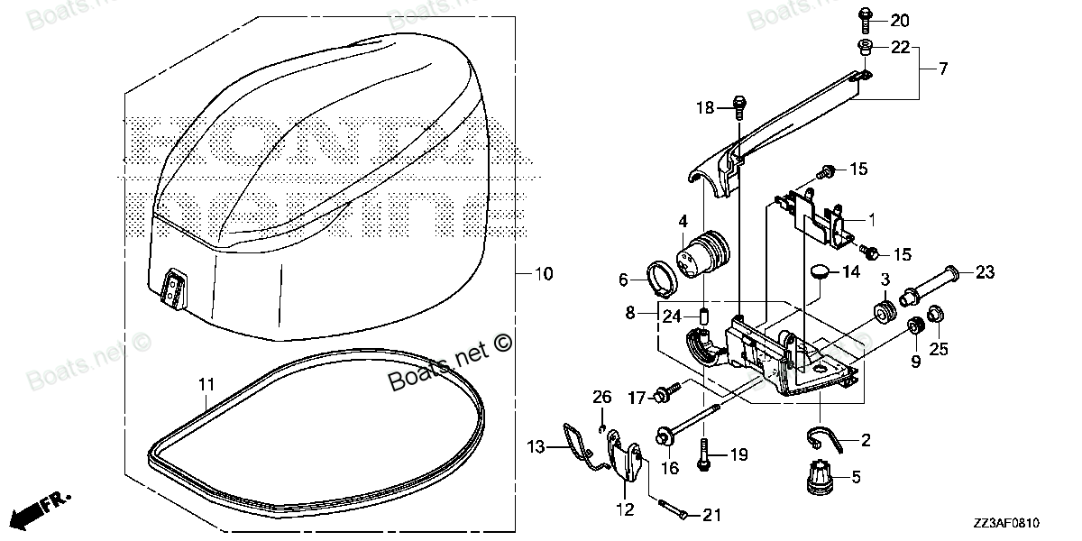
63100-ZZ3-010ZA COVER ASSY., ENGINE *NHB14M* (AQUA MARINE SILVER METARIC) Honda
BF60AK1 LRTA, BF60AK1 XRTA, BFP60AK1 LRTA, BFP60AK1 LRTB, BFP60AK1 XRTA
COVER
 Honda parts")
Price: query
Rating:
You can buy parts:
As an associate, we earn commssions on qualifying purchases through the links below
$597.97
24-09-2017
20.00[9.00] pounds
Honda: Honda
Honda 63100-ZZ3-010ZA Cover, Engine *Nhb14M*; 63100ZZ3010ZA Made by Honda
New
New
Number on catalog scheme: 10
Compatible models:
Honda entire parts catalog list:
- ENGINE COVER » 63100-ZZ3-010ZA
- ENGINE COVER » 63100-ZZ3-010ZA
- ENGINE COVER » 63100-ZZ3-010ZA
- ENGINE COVER » 63100-ZZ3-010ZA
- ENGINE COVER » 63100-ZZ3-010ZA
Information:
Start By:a. remove valve covers Call out (1) and (2) are not used in this removal procedure. Call outs begin with number (3). 1. Remove bolts (3) that hold the valve cover bases to the cylinder head assembly. Remove valve cover bases (4).
To prevent damage to the fuel injection nozzle, hold adapter assembly (5) in position at the end of the injection nozzle (6) when fuel line nut (7) is loosened or tightened.
2. Use Tool (A) and a 5P-0328 Crow Foot (7/8 in)to loosen the fuel injection line nut at the nozzle end. 3. Use Tool (B) to loosen the nut at the fuel injection line adapter end. Remove inner fuel injection lines (8). Install caps and plugs on all fuel injection line openings to keep dirt out of the fuel system. 4. Remove bolts (9) that hold the rocker shaft assemblies to the cylinder head assembly.5. Remove rocker shaft assemblies (10). 6. Put identification marks on the push rods as to their location in the engine. Remove push rods (11). 7. Put identification marks on the bridges as to their location in the engine. Remove bridges (12) from the dowels on the cylinder head assembly.Install Rocker Shaft Assemblies & Push Rods 1102 & 1208-012
1. Put clean engine oil on the bridges and dowels. Install the original bridges in their respective locations. New bridges can be mixed.2. Install bridges (1) on the bridge dowels. While firmly pressing 0.5 to 4.5 kg (1 to 10 lb)straight down on the top contact surface of the bridge, turn the adjusting screw clockwise until contact is made with the valve stem. Turn the screw an additional 20 to 30 degrees (1/3 to 1/2 of 1 hex on nut).This will straighten the dowel in the guide and compensate for the slack in the threads. Hold the adjusting screw in this position and tighten the locknut to a torque of 30 4 N m (22 3 lb ft). Install the original push rods in their respective locations in the engine. New push rods can be mixed.3. Install push rods (2). 4. Put rocker shaft assemblies (3) in position on the cylinder head assembly.5. Put clean engine oil on the threads of the bolts that hold the rocker shaft assemblies in place. Tighten the bolts first to a torque of 270 25 N m (200 18 lb ft).Start with the bolt in the center of the rocker shaft assembly. Tighten the bolts again to a torque of 450 20 N m (330 15 lb ft).Tighten the bolts again by hand to a torque of 450 20 N m (330 15 lb ft).
Do not cause damage to the O-ring seals on the inner fuel lines.
6. Install inner fuel injection lines (4). Tighten the fuel injection line adapter nuts (5) to a torque of 40 7 N m (30 5 lb ft)with Tool (A).
Do not let the tops of the fuel nozzles turn when the fuel lines are tightened. The nozzles will be damaged if the top of the nozzles turns in the body.
7. Tighten fuel injection line nut (6) to a torque of 40 7 N m (30 5 lb ft)with Tool (B) and a 5P-0328 (7/8 in) Crow Foot wrench.8. Make adjustments to the valves until the intake valve clearance is 0.38 mm (.015 in)and the exhaust valve clearance 0.76 mm (.030 in).See the topic "Valve Clearance Setting" in Systems Operation Testing & Adjusting Manual. Tighten the locknut to a torque of 30 4 N m (22 3 lb ft)and check the adjustments. 9. Install valve cover bases (7) on the cylinder head assembly. Install bolts that hold the valve cover bases in place. Tighten the bolts to a torque of 14 3 N m (10 2 lb ft).End By:a. install valve covers
Parts cover Honda:
24812-ZW7-U01

24812-ZW7-U01 COVER, GRIP (Honda Code 6799548).
BF115A1 LA, BF115A1 LCA, BF115A1 XA, BF115A1 XCA, BF115A2 LA, BF115A2 LCA, BF115A2 XA, BF115A2 XCA, BF115A3 LA, BF115A3 LCA, BF115A3 XA, BF115A3 XCA, BF115A4 LA, BF115A4 LCA, BF115A4 XA, BF115A4 XCA, BF115A5 LA, BF115A5 LCA, BF115A5 XA, BF115A5 XCA,
24814-ZW7-U01
24814-ZW7-U01 COVER, LOCK ARM (Honda Code 6799597).
BF115A1 LA, BF115A1 LCA, BF115A1 XA, BF115A1 XCA, BF115A2 LA, BF115A2 LCA, BF115A2 XA, BF115A2 XCA, BF115A3 LA, BF115A3 LCA, BF115A3 XA, BF115A3 XCA, BF115A4 LA, BF115A4 LCA, BF115A4 XA, BF115A4 XCA, BF115A5 LA, BF115A5 LCA, BF115A5 XA, BF115A5 XCA,
24812-ZW5-U01
24812-ZW5-U01 COVER, L. GRIP (Honda Code 6799522).
BF115A1 LA, BF115A1 LCA, BF115A1 XA, BF115A1 XCA, BF115A2 LA, BF115A2 LCA, BF115A2 XA, BF115A2 XCA, BF115A3 LA, BF115A3 LCA, BF115A3 XA, BF115A3 XCA, BF115A4 LA, BF115A4 LCA, BF115A4 XA, BF115A4 XCA, BF115A5 LA, BF115A5 LCA, BF115A5 XA, BF115A5 XCA,
24813-ZW5-U21
24813-ZW5-U21 COVER, DUAL GRIP (Honda Code 6799563).
BF115A1 LA, BF115A1 LCA, BF115A1 XA, BF115A1 XCA, BF115A2 LA, BF115A2 LCA, BF115A2 XA, BF115A2 XCA, BF115A3 LA, BF115A3 LCA, BF115A3 XA, BF115A3 XCA, BF115A4 LA, BF115A4 LCA, BF115A4 XA, BF115A4 XCA, BF115A5 LA, BF115A5 LCA, BF115A5 XA, BF115A5 XCA,
63710-ZZ3-000ZA
63710-ZZ3-000ZA COVER ASSY., R. ENGINE (LOWER) *NHB14M* (AQUA MARINE SILVER METARIC)
BF60AK1 LRTA, BF60AK1 XRTA, BFP60AK1 LRTA, BFP60AK1 LRTB, BFP60AK1 XRTA
63715-ZZ3-000ZA
63715-ZZ3-000ZA COVER ASSY., L. ENGINE (LOWER) *NHB14M* (AQUA MARINE SILVER METARIC)
BF60AK1 LRTA, BF60AK1 XRTA, BFP60AK1 LRTA, BFP60AK1 LRTB, BFP60AK1 XRTA
63731-ZZ3-000ZB
63731-ZZ3-000ZB COVER, R. MOUNTING (LOWER) *NHB14M* (AQUA MARINE SILVER METARIC)
BF60AK1 LRTA, BF60AK1 XRTA, BFP60AK1 LRTA, BFP60AK1 LRTB, BFP60AK1 XRTA
38216-ZZ3-003
38216-ZZ3-003 COVER ASSY., FUSE (40A)
BF60AK1 LRTA, BF60AK1 XRTA, BFP60AK1 LRTA, BFP60AK1 LRTB, BFP60AK1 XRTA