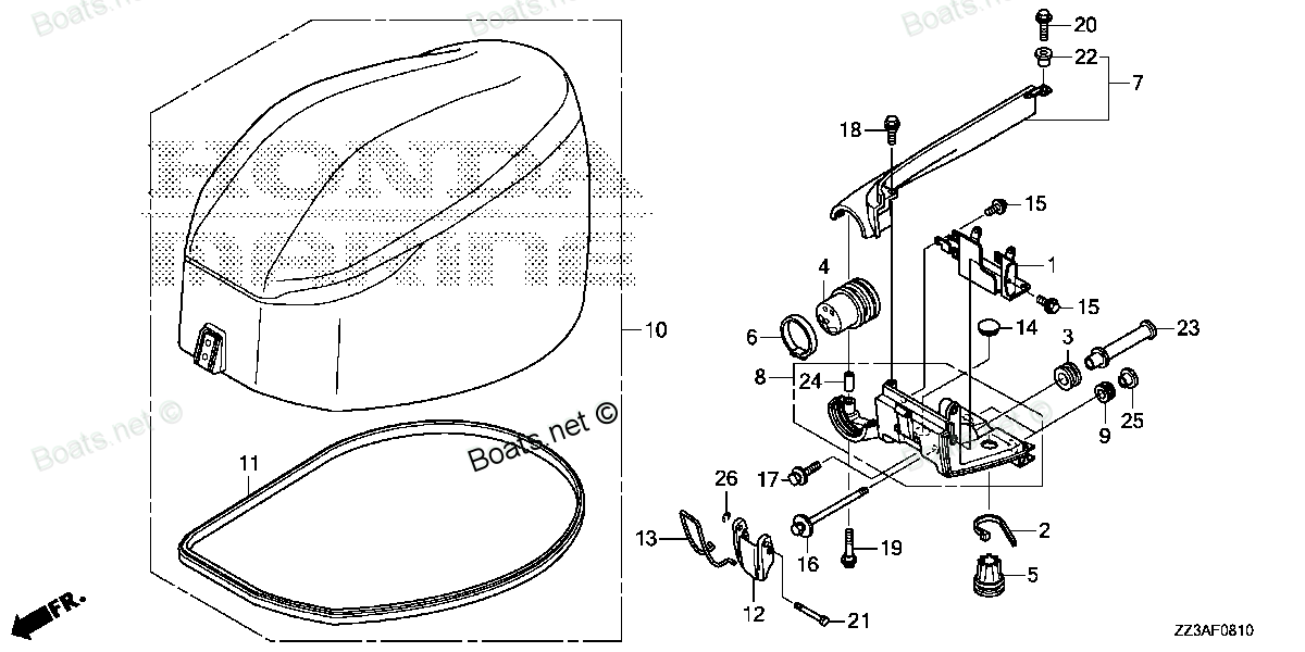
40105-ZZ3-000 GROMMET, REMOTE CONTROL CABLE Honda
BF60AK1 LRTA, BF60AK1 XRTA, BFP60AK1 LRTA, BFP60AK1 LRTB, BFP60AK1 XRTA
GROMMET

Price: query
Rating:
You can buy parts:
As an associate, we earn commssions on qualifying purchases through the links below

Number on catalog scheme: 4
Compatible models:
Honda entire parts catalog list:
- ENGINE COVER » 40105-ZZ3-000
- ENGINE COVER » 40105-ZZ3-000
- ENGINE COVER » 40105-ZZ3-000
- ENGINE COVER » 40105-ZZ3-000
- ENGINE COVER » 40105-ZZ3-000
Information:
1. Put the engine in position on tooling (A) as shown. 2. Turn the crankshaft until the timing mark "C" on crankshaft gear (1) is in alignment with the timing mark "C" on camshaft gear (2) as shown in inset. 3. Remove nuts (4) that hold connecting rod caps (3) to the connecting rods. Remove the rod caps. The connecting rod bolts are loose on the connecting rod and can fall out when the nuts are removed.4. Remove the connecting rod bolts from the connecting rods.
If the piston and connecting rod assemblies are pushed down too far in the cylinder liners, the piston can hit the fuel injection nozzle or the intake exhaust valve which can cause damage to the fuel injection nozzle or the piston.
If the intake and exhaust valves are closed it can be difficult to push the piston and connecting rod assembly down in the cylinder liner. 5. Push No. 2, 3, 4, 5 piston and connecting rod assemblies (5) down in the cylinder liners far enough to clear the crankshaft. Move connecting rod away from the crankshaft. 6. Remove main bearing cap bolts (7) and remove main bearing caps (6). 7. Remove thrust bearings (8) from the No. 7 main bearing. 8. Install tooling (B) to crankshaft (9). Fasten a hoist to tooling (A). Lift crankshaft (9) straight up from the cylinder block. 9. Use tooling (C) to remove the gear from the crankshaft. The weight of the crankshaft is 95 kg (210 lb.). 10. If necessary remove main bearings (10) from the cylinder block and main bearing caps. Remove rod bearings (11) from the connecting rods and rod bearing caps.Install Crankshaft
1. Put the engine in position on tooling (A). Install the bearings dry when the clearance checks are made. Put clean engine oil on all the bearings for final assembly.
Make sure the upper and lower halves of the main bearings are installed so the bearing tabs fit into the notch in the cylinder block and main bearing caps.
2. If the bearings were removed from the engine, clean the bearing surfaces in the cylinder block and the connecting rods. Install the upper halves of connecting rod bearings (1) and main bearings (2). 3. Heat crankshaft gear (3) to a maximum temperature of 315°C (600°F). Install the gear on the crankshaft. 4. Install tooling (B) and tooling (C) on the crankshaft. Fasten a hoist to the crankshaft and put crankshaft (4) in position in the cylinder block with timing mark "C" on the crankshaft gear (5) with the timing mark "C" on the camshaft gear (6). No. 1 and 6 connecting rods must be in alignment with their respective crankshaft journals when the crankshaft is installed in the block. When the bearing clearance is checked and the engine is in a vertical position, such as in the vehicle, the crankshaft will have to be lifted up and held against the upper halves of the main bearings to get a correct measurement with the Plastigage. The Plastigage will not hold the weight of the crankshaft and give a correct indication. If the engine is in a horizontal position, it is not necessary to hold the crankshaft up. Do not turn the crankshaft when the Plastigage is in position to check clearances.5. Check the main bearing clearances with Plastigage (D) as follows: a) Put a piece of Plastigage (D) in position as shown.
Make sure the part number on the main bearing cap is toward the front of the engine and the number on the main bearing cap is the same as the number on the cylinder block on the left side of each main bearing cap.
Do not turn the crankshaft when Plastigage (D) is in position.b) Install main bearing cap (7). Put clean engine oil on the bolt threads and the face of the washers and install the bolts. Tighten the bolts to a torque of 40 4 N m (30 3 lb.ft.).
Do not use an impact wrench to tighten the bolts the additional 90°.
c) Put a mark on each bolt and main bearing cap, then tighten the bolts 90° more.d) Remove the main bearing caps. Remove Plastigage (D) and measure the width of the Plastigage. The main bearing clearance must be 0.076 to 0.165 mm (.0030 to .0065 in.). The maximum permissible clearance with used bearings is 0.25 mm (.010 in.). 6. Put clean oil on thrust bearing (9) for the No. 7 main bearing. Install the thrust bearing with the identification "BLOCK SIDE" toward the cylinder block and the tabs on the thrust bearings in the machined area in the cylinder block. Tabs (8) will not let the thrust bearings be installed backward. On early model thrust bearings, make sure notches (10) in the thrust bearing are installed toward the crankshaft. 7. Install main bearing caps (7) and tighten bolts as in Steps 5b and 5c. 8. Check the crankshaft end play with tooling (E). The end play is controlled by the thrust bearings on the No. 7 main bearing. End play with new bearings is 0.064 to 0.368 mm (.0025 to .0145 in.). The maximum permissible end play with used bearings is 0.64 mm (.025 in.). 9. Move No. 2, 3, 4 and 5 connecting rods in position under the crankshaft. Pull connecting rod and piston assemblies (11) into position against the crankshaft. Install the connecting rod bearings dry when the clearance checks are made. Put clean engine oil on the connecting rod bearings for final assembly. 10. Install lower half of the rod bearing (12) in the connecting rod cap. Be sure the tabs in the back of the connecting rod bearings are in the tab grooves of the connecting rod and cap.11. Use Plastigage (D) to check the connecting rod bearing clearance.12. Put Plastigage (D) in position on the crankshaft as shown.13. Put clean engine oil on the threads of the rod bolts and seat surfaces of the nuts.
When connecting rod caps are installed, make sure the number on the
Parts grommet Honda:
40102-ZV5-000

40102-ZV5-000 GROMMET, CASE (LOWER) (Honda Code 3704343).
BF115A1 LA, BF115A1 LCA, BF115A1 XA, BF115A1 XCA, BF115A2 LA, BF115A2 LCA, BF115A2 XA, BF115A2 XCA, BF115A3 LA, BF115A3 LCA, BF115A3 XA, BF115A3 XCA, BF115A4 LA, BF115A4 LCA, BF115A4 XA, BF115A4 XCA, BF115A5 LA, BF115A5 LCA, BF115A5 XA, BF115A5 XCA,
24839-ZW1-V01
24839-ZW1-V01 GROMMET (Honda Code 4898912).
BF115A1 LA, BF115A1 LCA, BF115A1 XA, BF115A1 XCA, BF115A2 LA, BF115A2 LCA, BF115A2 XA, BF115A2 XCA, BF115A3 LA, BF115A3 LCA, BF115A3 XA, BF115A3 XCA, BF115A4 LA, BF115A4 LCA, BF115A4 XA, BF115A4 XCA, BF115A5 LA, BF115A5 LCA, BF115A5 XA, BF115A5 XCA,
16733-ZW5-000
16733-ZW5-000 GROMMET, VAPOR SEPARATOR (Honda Code 5890934).
BF115A1 LA, BF115A1 LCA, BF115A1 XA, BF115A1 XCA, BF115A2 LA, BF115A2 LCA, BF115A2 XA, BF115A2 XCA, BF115A3 LA, BF115A3 LCA, BF115A3 XA, BF115A3 XCA, BF115A4 LA, BF115A4 LCA, BF115A4 XA, BF115A4 XCA, BF115A5 LA, BF115A5 LCA, BF115A5 XA, BF115A5 XCA,
37881-P2A-000

37881-P2A-000 GROMMET, TA SENSOR (Honda Code 4843074).
BF115DK1 LA, BF115DK1 XA, BF115DK1 XCA, BF135A4 LA, BF135A4 XA, BF135A4 XCA, BF135A5 LA, BF135A5 XA, BF135A5 XCA, BF135A6 LA, BF135A6 XA, BF135A6 XCA, BF135AK0 LA, BF135AK0 XA, BF135AK0 XCA, BF135AK2 LA, BF135AK2 XA, BF135AK2 XCA, BF150A4 LA, BF150A4
50142-437-970
50142-437-970 GROMMET, SIDE COVER (Honda Code 1303379).
BF25DK0 LRGA, BF25DK0 LRTA, BF25DK0 SHGA, BF25DK2 LRGA, BF25DK2 LRTA, BF25DK2 SHGA, BF25DK3 LRGA, BF25DK3 LRTA, BF25DK3 SHGA, BF30DK0 LRGA, BF30DK0 LRTA, BF30DK0 SRTA, BF30DK2 LRGA, BF30DK2 LRTA, BF30DK2 SRTA, BF30DK3 LRGA, BF30DK3 LRTA, BF30DK3 SRTA
17374-ZZ5-000
17374-ZZ5-000 GROMMET, AIR GUIDE
BF40DK2 LHA, BF40DK2 LRTA, BF50DK2 LRTA, BF50DK2 XRTA, BF60AK1 LRTA, BF60AK1 XRTA, BFP60AK1 LRTA, BFP60AK1 LRTB, BFP60AK1 XRTA
53115-ZZ3-A41
53115-ZZ3-A41 GROMMET, POWER TILT SWITCH
BF60AK1 LRTA, BF60AK1 XRTA, BFP60AK1 LRTA, BFP60AK1 LRTB, BFP60AK1 XRTA
53126-ZZ3-A41