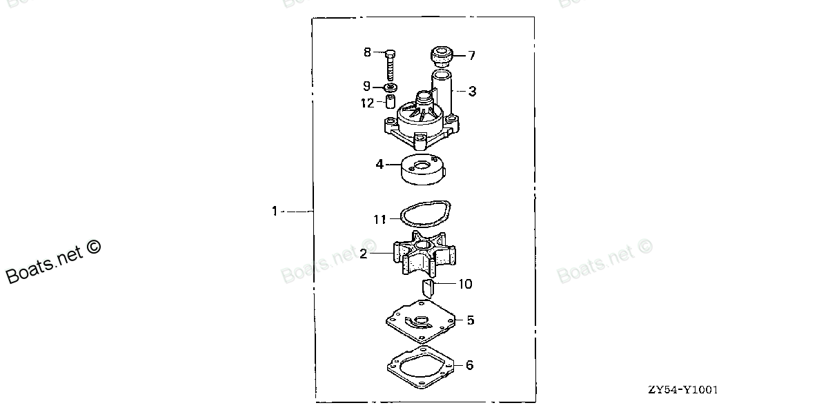
19221-ZY6-000 HOUSING, IMPELLER Honda
BF135A4 LA, BF135A4 XA, BF135A4 XCA, BF135A5 LA, BF135A5 XA, BF135A5 XCA, BF135A6 LA, BF135A6 XA, BF135A6 XCA, BF135AK0 LA, BF135AK0 XA, BF135AK0 XCA, BF150A4 LA, BF150A4 XA, BF150A4 XCA, BF150A5 LA, BF150A5 XA, BF150A5 XCA, BF150A6 LA, BF150A6 XA, B
HOUSING

Price: query
Rating:
Number on catalog scheme: 3
Compatible models:
BF135A4 LA
BF135A4 XA
BF135A4 XCA
BF135A5 LA
BF135A5 XA
BF135A5 XCA
BF135A6 LA
BF135A6 XA
BF135A6 XCA
BF135AK0 LA
BF135AK0 XA
BF135AK0 XCA
BF150A4 LA
BF150A4 XA
BF150A4 XCA
BF150A5 LA
BF150A5 XA
BF150A5 XCA
BF150A6 LA
BF150A6 XA
BF150A6 XCA
BF150AK0 LA
BF150AK0 XA
BF150AK0 XCA
BF75DK0 LHTA
BF75DK0 LRTA
BF75DK2 LRTA
BF90DK0 LHTA
BF90DK0 LRTA
BF90DK0 XRTA
BF90DK2 LRTA
BF90DK2 XRTA
Honda
Honda entire parts catalog list:
- WATER PUMP IMPELLER KIT (2) » 19221-ZY6-000
- WATER PUMP VERTICAL SHAFT » 19221-ZY6-000
- WATER PUMP VERTICAL SHAFT » 19221-ZY6-000
- WATER PUMP IMPELLER KIT (2) » 19221-ZY6-000
- WATER PUMP IMPELLER KIT (2) » 19221-ZY6-000
- WATER PUMP VERTICAL SHAFT » 19221-ZY6-000
- WATER PUMP VERTICAL SHAFT » 19221-ZY6-000
- WATER PUMP IMPELLER KIT (2) » 19221-ZY6-000
- WATER PUMP IMPELLER KIT (2) » 19221-ZY6-000
- WATER PUMP VERTICAL SHAFT » 19221-ZY6-000
- WATER PUMP IMPELLER KIT (2) » 19221-ZY6-000
- WATER PUMP VERTICAL SHAFT » 19221-ZY6-000
- WATER PUMP IMPELLER KIT (2) » 19221-ZY6-000
- WATER PUMP VERTICAL SHAFT » 19221-ZY6-000
- WATER PUMP IMPELLER KIT (2) » 19221-ZY6-000
- WATER PUMP VERTICAL SHAFT » 19221-ZY6-000
- WATER PUMP VERTICAL SHAFT » 19221-ZY6-000
- WATER PUMP IMPELLER KIT (2) » 19221-ZY6-000
- WATER PUMP IMPELLER KIT (2) » 19221-ZY6-000
- WATER PUMP VERTICAL SHAFT » 19221-ZY6-000
- WATER PUMP VERTICAL SHAFT » 19221-ZY6-000
- WATER PUMP IMPELLER KIT (2) » 19221-ZY6-000
- WATER PUMP IMPELLER KIT (2) » 19221-ZY6-000
- WATER PUMP VERTICAL SHAFT » 19221-ZY6-000
- WATER PUMP VERTICAL SHAFT » 19221-ZY6-000
- WATER PUMP IMPELLER KIT (2) » 19221-ZY6-000
- WATER PUMP IMPELLER KIT (2) » 19221-ZY6-000
- WATER PUMP VERTICAL SHAFT » 19221-ZY6-000
- WATER PUMP IMPELLER KIT (2) » 19221-ZY6-000
- WATER PUMP VERTICAL SHAFT » 19221-ZY6-000
- WATER PUMP VERTICAL SHAFT » 19221-ZY6-000
- WATER PUMP IMPELLER KIT (2) » 19221-ZY6-000
- WATER PUMP IMPELLER KIT (2) » 19221-ZY6-000
- WATER PUMP VERTICAL SHAFT » 19221-ZY6-000
- WATER PUMP VERTICAL SHAFT » 19221-ZY6-000
- WATER PUMP IMPELLER KIT (2) » 19221-ZY6-000
- WATER PUMP IMPELLER KIT (2) » 19221-ZY6-000
- WATER PUMP VERTICAL SHAFT » 19221-ZY6-000
- WATER PUMP IMPELLER KIT (2) » 19221-ZY6-000
- WATER PUMP VERTICAL SHAFT » 19221-ZY6-000
- WATER PUMP VERTICAL SHAFT » 19221-ZY6-000
- WATER PUMP IMPELLER KIT (2) » 19221-ZY6-000
- WATER PUMP IMPELLER KIT (2) » 19221-ZY6-000
- WATER PUMP VERTICAL SHAFT » 19221-ZY6-000
- WATER PUMP VERTICAL SHAFT » 19221-ZY6-000
- WATER PUMP IMPELLER KIT (2) » 19221-ZY6-000
- WATER PUMP IMPELLER KIT (2) » 19221-ZY6-000
- WATER PUMP VERTICAL SHAFT » 19221-ZY6-000
- IMPELLER PUMP KIT » 19221-ZY6-000
- WATER PUMP VERTICAL SHAFT » 19221-ZY6-000
- WATER PUMP VERTICAL SHAFT » 19221-ZY6-000
- IMPELLER PUMP KIT » 19221-ZY6-000
- IMPELLER PUMP KIT » 19221-ZY6-000
- WATER PUMP VERTICAL SHAFT » 19221-ZY6-000
- IMPELLER PUMP KIT » 19221-ZY6-000
- WATER PUMP VERTICAL SHAFT » 19221-ZY6-000
- WATER PUMP VERTICAL SHAFT » 19221-ZY6-000
- IMPELLER PUMP KIT » 19221-ZY6-000
- IMPELLER PUMP KIT » 19221-ZY6-000
- WATER PUMP VERTICAL SHAFT » 19221-ZY6-000
- IMPELLER PUMP KIT » 19221-ZY6-000
- WATER PUMP VERTICAL SHAFT » 19221-ZY6-000
- WATER PUMP VERTICAL SHAFT » 19221-ZY6-000
- IMPELLER PUMP KIT » 19221-ZY6-000
Information:
1. Loosen clamps (1) then remove turbocharger tube (2). 2. Remove the clamps that hold breather tube (3) to the valve cover and the cylinder block. Remove breather tube (3).3. Remove the bolts that hold elbow (4) to the water temperature regulator housing. Remove elbow (4).4. Remove water lines (7) from the water pump.5. Remove engine oil cooler (5) from the water pump.6. See the illustration for the correct location of the bolts that hold the water pump to the timing gear plate. The bolts that have identification (X) only must be removed to remove the water pump.7. Remove water pump (6). Remove the gasket from the timing gear plate. The following steps are for the installation of the water pump.8. Put water pump (6) and a new gasket in position on the timing gear plate. Install the bolts that hold it in position on the timing gear plate.9. Put clean SAE 30 oil on the O-ring seals on elbow (4). Put elbow (4) in position on the water pump. Install the bolts that hold it to the water temperature regulator housing.10. Install engine oil cooler (5) on the water pump.11. Install water lines (7) on the water pump.12. Put breather tube (3) in position. Install the clamps that hold the breather tube to the valve cover and the cylinder block.13. Install turbocharger tube (2) and then tighten clamps (1).Disassemble & Assemble Water Pump
The water pump seal can be replaced without removing the water pump from the engine. An intermittent leakage of a small amount of coolant from the hole in the water pump housing is not an indication of a water pump seal failure. This is required to provide lubrication for the seal. Replace the water pump seal only if a large amount of leakge or a constant flow of coolant is observed draining from the water pump housing.1. Remove O-ring seal (3) from adapter (4). Remove the adapter from housing (7). Remove the O-ring seal from the outside of the adapter.2. Remove bolt (1) and washer (2). Use tooling (A) to remove impeller (6) from shaft (13).3. Remove spring and seal (5) from the shaft.4. Remove four bolts (16) from retainer (12) that hold the shaft assembly to the pump housing. Remove O-ring seal (18) from housing (7).5. Remove gear and shaft assembly (17) from the housing. Remove bolt (15), retainer (14) and retainer (12) from the shaft assembly.6. Use a press to remove shaft (13) from the gear. Remove bearing (9), spacer (10) and bearing (11) from the shaft.7. Remove lip-type seal (8) from the housing.8. Turn the housing over, and remove ceramic ring (20) and seal (19) from the housing. The following steps are for the assembly of the water pump.9. Use 6V1541 Quick Cure Primer and clean shaft (13) and the seal counter bore in the pump housing.10. Install bearing (9), spacer (10) and bearing (11) on shaft (13).11. Put retainer (12) and gear (17) on the shaft assembly. Install retainer (14) and bolt (15) on the shaft.12. Use tooling (B) to install lip-type seal (8) in housing (7). Install seal with the lip toward the inside of the housing. Put a small amount of clean SAE 30 oil on the lip of the seal.13. Install a new O-ring seal (18) on the housing.14. Put gear and shaft assembly (17) in position in the housing. Install bolts (16) that hold retainer (12) to the housing.
Clean water only is permitted for use as a lubricant for assistance at installation. Do not damage or put hands on the wear surface of the carbon ring or the ceramic ring. Install the ceramic ring with the smoothest face of the ring toward the carbon seal assembly.
15. Put ceramic ring (20) in position in seal (19). Use hand pressure and tool (C) to install the ceramic ring in the housing.
Avoid contaminating the seal faces with grease or oil. Also, avoid stretching the rubber seal during installation.
The carbon seal assembly must rotate with the water pump shaft after installation.16. Separate spring and seal (5). Use hand pressure and tool (C) to install the seal on the shaft of the gear and shaft assembly (17). Push the seal on the shaft until the seal faces make light contact. Install the spring on the shaft.17. Put impeller (6) in position on the shaft. Install washer (2) and bolt (1) that hold the impeller. Tighten the bolt to a torque of 39 3 N m (29 2 lb ft).18. Install the O-ring seal on the outside diameter of adapter (4). Put a small amount of clean SAE 30 on the O-ring seal.19. Install O-ring seal (3) on the adapter.20. Put adapter (4) in position on the housing.End By:a. install water pump
Parts housing Honda:
24830-ZV5-010

24830-ZV5-010 HOUSING, REMOTE CONTROL BOX (Honda Code 4210894). (B)
BF115A1 LA, BF115A1 LCA, BF115A1 XA, BF115A1 XCA, BF115A2 LA, BF115A2 LCA, BF115A2 XA, BF115A2 XCA, BF115A3 LA, BF115A3 LCA, BF115A3 XA, BF115A3 XCA, BF115A4 LA, BF115A4 LCA, BF115A4 XA, BF115A4 XCA, BF115A5 LA, BF115A5 LCA, BF115A5 XA, BF115A5 XCA,
24820-ZW5-U21
24820-ZW5-U21 HOUSING, DUAL REMOTE CONTROL (Honda Code 6799662). BOX
BF115A1 LA, BF115A1 LCA, BF115A1 XA, BF115A1 XCA, BF115A2 LA, BF115A2 LCA, BF115A2 XA, BF115A2 XCA, BF115A3 LA, BF115A3 LCA, BF115A3 XA, BF115A3 XCA, BF115A4 LA, BF115A4 LCA, BF115A4 XA, BF115A4 XCA, BF115A5 LA, BF115A5 LCA, BF115A5 XA, BF115A5 XCA,
24820-ZW5-U01
24820-ZW5-U01 HOUSING, REMOTE CONTROL BOX (Honda Code 6799654).
BF115A1 LA, BF115A1 LCA, BF115A1 XA, BF115A1 XCA, BF115A2 LA, BF115A2 LCA, BF115A2 XA, BF115A2 XCA, BF115A3 LA, BF115A3 LCA, BF115A3 XA, BF115A3 XCA, BF115A4 LA, BF115A4 LCA, BF115A4 XA, BF115A4 XCA, BF115A5 LA, BF115A5 LCA, BF115A5 XA, BF115A5 XCA,
19221-ZY6-A00
19221-ZY6-A00 HOUSING, IMPELLER
BF115DK1 LA, BF115DK1 XA, BF115DK1 XCA, BF135A4 LA, BF135A4 XA, BF135A4 XCA, BF135A5 LA, BF135A5 XA, BF135A5 XCA, BF135A6 LA, BF135A6 XA, BF135A6 XCA, BF135AK0 LA, BF135AK0 XA, BF135AK0 XCA, BF135AK2 LA, BF135AK2 XA, BF135AK2 XCA, BF150A4 LA, BF150A4
41117-ZY6-000
41117-ZY6-000 HOUSING, WATER SEAL
BF135A4 LA, BF135A4 XA, BF135A4 XCA, BF135A5 LA, BF135A5 XA, BF135A5 XCA, BF135A6 LA, BF135A6 XA, BF135A6 XCA, BF135AK0 LA, BF135AK0 XA, BF135AK0 XCA, BF150A4 LA, BF150A4 XA, BF150A4 XCA, BF150A5 LA, BF150A5 XA, BF150A5 XCA, BF150A6 LA, BF150A6 XA, B
41117-ZZ3-000
41117-ZZ3-000 HOUSING, WATER SEAL
BF115DK1 LA, BF115DK1 XA, BF115DK1 XCA, BF135AK0 LA, BF135AK0 XA, BF135AK0 XCA, BF135AK2 LA, BF135AK2 XA, BF135AK2 XCA, BF150AK0 LA, BF150AK0 XA, BF150AK0 XCA, BF150AK2 LA, BF150AK2 XA, BF150AK2 XCA, BF60AK1 LRTA, BF60AK1 XRTA
50161-ZW1-020ZB
50161-ZW1-020ZB HOUSING, CENTER MOUNTING (LOWER) *NHB14M* (AQUA MARINE SILVER METARIC)
BF115DK1 LA, BF115DK1 XA, BF115DK1 XCA, BF135AK2 LA, BF135AK2 XA, BF135AK2 XCA, BF150AK2 LA, BF150AK2 XA, BF150AK2 XCA, BF75DK2 LRTA, BF90DK2 LRTA, BF90DK2 XRTA
41117-ZY6-010
41117-ZY6-010 HOUSING, WATER SEAL (Honda Code 9178740).
BF135AK0 LA, BF135AK0 XA, BF135AK0 XCA, BF150AK0 LA, BF150AK0 XA, BF150AK0 XCA