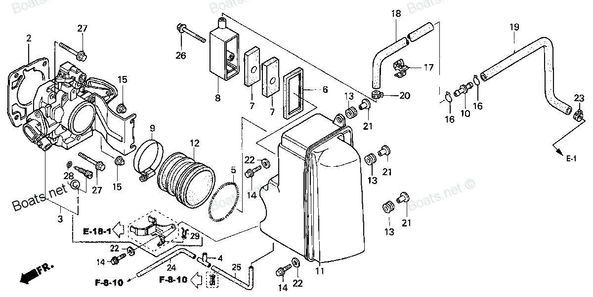
17201-MG9-000 JOINT, VACUUM TUBE (A) (Honda Code 1523992). Honda
BF115A1 LA, BF115A1 LCA, BF115A1 XA, BF115A1 XCA, BF115A2 LA, BF115A2 LCA, BF115A2 XA, BF115A2 XCA, BF115A3 LA, BF115A3 LCA, BF115A3 XA, BF115A3 XCA, BF115A4 LA, BF115A4 LCA, BF115A4 XA, BF115A4 XCA, BF115A5 LA, BF115A5 LCA, BF115A5 XA, BF115A5 XCA,
JOINT
 (Honda Code 1523992). Honda parts")
Price: query
Rating:
You can buy parts:
As an associate, we earn commssions on qualifying purchases through the links below

$12.82
28-12-2023
0.25[0.11] pounds
US: HONDA-KTMSOUTHGA
Honda 17201-MG9-000 Joint A Vacuum Tube
Honda Honda 17201-MG9-000 Joint A Vacuum Tube
Honda Honda 17201-MG9-000 Joint A Vacuum Tube
Number on catalog scheme: 4
Compatible models:
BF115A1 LA
BF115A1 LCA
BF115A1 XA
BF115A1 XCA
BF115A2 LA
BF115A2 LCA
BF115A2 XA
BF115A2 XCA
BF115A3 LA
BF115A3 LCA
BF115A3 XA
BF115A3 XCA
BF115A4 LA
BF115A4 LCA
BF115A4 XA
BF115A4 XCA
BF115A5 LA
BF115A5 LCA
BF115A5 XA
BF115A5 XCA
BF115A6 LA
BF115A6 LCA
BF115A6 XA
BF115A6 XCA
BF115AK0 LA
BF115AK0 XA
BF115AX LA
BF115AX LCA
BF115AX XA
BF115AX XCA
BF115AY LA
BF115AY LCA
BF115AY XA
BF115AY XCA
BF130A1 LA
BF130A1 LCA
BF130A1 XA
BF130A1 XCA
BF130A2 LA
BF130A2 LCA
BF130A2 XA
BF130A2 XCA
BF130A3 LA
BF130A3 LCA
BF130A3 XA
BF130A3 XCA
BF130A4 LA
BF130A4 LCA
BF130A4 XA
BF130A4 XCA
BF130AX LA
BF130AX LCA
BF130AX XA
BF130AX XCA
BF130AY LA
BF130AY LCA
BF130AY XA
BF130AY XCA
BF175AK1 LA
BF175AK1 XA
BF175AK1 XCA
BF175AK2 LA
BF175AK2 XA
BF175AK2 XCA
BF200A2 LA
BF200A2 XA
BF200A2 XCA
BF200A2 XXA
BF200A2 XXCA
BF200A3 LA
BF200A3 XA
BF200A3 XCA
BF200A3 XXA
BF200A3 XXCA
BF200A4 LA
BF200A4 XA
BF200A4 XCA
BF200A4 XXA
BF200A4 XXCA
BF200A5 LA
BF200A5 XA
BF200A5 XCA
BF200A5 XXA
BF200A5 XXCA
BF200A6 LA
BF200A6 XA
BF200A6 XCA
BF200A6 XXA
BF200A6 XXCA
BF200AK0 LA
BF200AK0 XA
BF200AK0 XCA
BF200AK1 LA
BF200AK1 XA
BF200AK1 XCA
BF200AK2 LA
BF200AK2 XA
BF200AK2 XCA
BF225A2 LA
BF225A2 XA
BF225A2 XCA
BF225A2 XXA
BF225A2 XXCA
BF225A3 LA
BF225A3 XA
BF225A3 XCA
BF225A3 XXA
BF225A3 XXCA
BF225A4 LA
BF225A4 XA
BF225A4 XCA
BF225A4 XXA
BF225A4 XXCA
BF225A5 LA
BF225A5 XA
BF225A5 XCA
BF225A5 XXA
BF225A5 XXCA
BF225A6 LA
BF225A6 XA
BF225A6 XCA
BF225A6 XXA
BF225A6 XXCA
BF225AK0 LA
BF225AK0 XA
BF225AK0 XCA
BF225AK0 XXA
BF225AK0 XXCA
BF225AK1 LA
BF225AK1 XA
BF225AK1 XCA
BF225AK1 XXA
BF225AK1 XXCA
BF225AK2 LA
BF225AK2 XA
BF225AK2 XCA
BF225AK2 XXA
BF225AK2 XXCA
BF250A LA
BF250A XA
BF250A XCA
BF250A XXA
BF250A XXCA
Honda
Honda entire parts catalog list:
- THROTTLE BODY » 17201-MG9-000
- THROTTLE BODY » 17201-MG9-000
- THROTTLE BODY » 17201-MG9-000
- THROTTLE BODY » 17201-MG9-000
- THROTTLE BODY » 17201-MG9-000
- THROTTLE BODY » 17201-MG9-000
- THROTTLE BODY » 17201-MG9-000
- THROTTLE BODY » 17201-MG9-000
- THROTTLE BODY » 17201-MG9-000
- THROTTLE BODY » 17201-MG9-000
- THROTTLE BODY » 17201-MG9-000
- THROTTLE BODY » 17201-MG9-000
- THROTTLE BODY » 17201-MG9-000
- THROTTLE BODY » 17201-MG9-000
- THROTTLE BODY » 17201-MG9-000
- THROTTLE BODY » 17201-MG9-000
- THROTTLE BODY » 17201-MG9-000
- THROTTLE BODY » 17201-MG9-000
- THROTTLE BODY » 17201-MG9-000
- THROTTLE BODY » 17201-MG9-000
- THROTTLE BODY » 17201-MG9-000
- THROTTLE BODY » 17201-MG9-000
- THROTTLE BODY » 17201-MG9-000
- THROTTLE BODY » 17201-MG9-000
- THROTTLE BODY » 17201-MG9-000
- THROTTLE BODY » 17201-MG9-000
- THROTTLE BODY » 17201-MG9-000
- THROTTLE BODY » 17201-MG9-000
- THROTTLE BODY » 17201-MG9-000
- THROTTLE BODY » 17201-MG9-000
- THROTTLE BODY » 17201-MG9-000
- THROTTLE BODY » 17201-MG9-000
- THROTTLE BODY » 17201-MG9-000
- THROTTLE BODY » 17201-MG9-000
- THROTTLE BODY » 17201-MG9-000
- THROTTLE BODY » 17201-MG9-000
- THROTTLE BODY » 17201-MG9-000
- THROTTLE BODY » 17201-MG9-000
- THROTTLE BODY » 17201-MG9-000
- THROTTLE BODY » 17201-MG9-000
- THROTTLE BODY » 17201-MG9-000
- THROTTLE BODY » 17201-MG9-000
- THROTTLE BODY » 17201-MG9-000
- THROTTLE BODY » 17201-MG9-000
- THROTTLE BODY » 17201-MG9-000
- THROTTLE BODY » 17201-MG9-000
- THROTTLE BODY » 17201-MG9-000
- THROTTLE BODY » 17201-MG9-000
- THROTTLE BODY » 17201-MG9-000
- THROTTLE BODY » 17201-MG9-000
- THROTTLE BODY » 17201-MG9-000
- THROTTLE BODY » 17201-MG9-000
- THROTTLE BODY » 17201-MG9-000
- THROTTLE BODY » 17201-MG9-000
- THROTTLE BODY » 17201-MG9-000
- THROTTLE BODY » 17201-MG9-000
- THROTTLE BODY » 17201-MG9-000
- THROTTLE BODY » 17201-MG9-000
- INTAKE MANIFOLD » 17201-MG9-000
- INTAKE MANIFOLD » 17201-MG9-000
- INTAKE MANIFOLD » 17201-MG9-000
- INTAKE MANIFOLD » 17201-MG9-000
- INTAKE MANIFOLD » 17201-MG9-000
- INTAKE MANIFOLD » 17201-MG9-000
- INTAKE MANIFOLD » 17201-MG9-000
- INTAKE MANIFOLD » 17201-MG9-000
- INTAKE MANIFOLD » 17201-MG9-000
- INTAKE MANIFOLD » 17201-MG9-000
- INTAKE MANIFOLD » 17201-MG9-000
- INTAKE MANIFOLD » 17201-MG9-000
- INTAKE MANIFOLD » 17201-MG9-000
- INTAKE MANIFOLD » 17201-MG9-000
- INTAKE MANIFOLD » 17201-MG9-000
- INTAKE MANIFOLD » 17201-MG9-000
- INTAKE MANIFOLD » 17201-MG9-000
- INTAKE MANIFOLD » 17201-MG9-000
- INTAKE MANIFOLD » 17201-MG9-000
- INTAKE MANIFOLD » 17201-MG9-000
- INTAKE MANIFOLD » 17201-MG9-000
- INTAKE MANIFOLD » 17201-MG9-000
- INTAKE MANIFOLD » 17201-MG9-000
- INTAKE MANIFOLD » 17201-MG9-000
- INTAKE MANIFOLD » 17201-MG9-000
- INTAKE MANIFOLD » 17201-MG9-000
- INTAKE MANIFOLD » 17201-MG9-000
- INTAKE MANIFOLD » 17201-MG9-000
- INTAKE MANIFOLD » 17201-MG9-000
- INTAKE MANIFOLD » 17201-MG9-000
- INTAKE MANIFOLD » 17201-MG9-000
- INTAKE MANIFOLD » 17201-MG9-000
- INTAKE MANIFOLD » 17201-MG9-000
- INTAKE MANIFOLD » 17201-MG9-000
- INTAKE MANIFOLD » 17201-MG9-000
- INTAKE MANIFOLD » 17201-MG9-000
- INTAKE MANIFOLD » 17201-MG9-000
- INTAKE MANIFOLD » 17201-MG9-000
- INTAKE MANIFOLD » 17201-MG9-000
- INTAKE MANIFOLD » 17201-MG9-000
- INTAKE MANIFOLD » 17201-MG9-000
- INTAKE MANIFOLD » 17201-MG9-000
- INTAKE MANIFOLD » 17201-MG9-000
- INTAKE MANIFOLD » 17201-MG9-000
- INTAKE MANIFOLD » 17201-MG9-000
- INTAKE MANIFOLD » 17201-MG9-000
- INTAKE MANIFOLD » 17201-MG9-000
- INTAKE MANIFOLD » 17201-MG9-000
- INTAKE MANIFOLD » 17201-MG9-000
- INTAKE MANIFOLD » 17201-MG9-000
- INTAKE MANIFOLD » 17201-MG9-000
- INTAKE MANIFOLD » 17201-MG9-000
- INTAKE MANIFOLD » 17201-MG9-000
- INTAKE MANIFOLD » 17201-MG9-000
- INTAKE MANIFOLD » 17201-MG9-000
- INTAKE MANIFOLD » 17201-MG9-000
- INTAKE MANIFOLD » 17201-MG9-000
Information:
If the application is equipped with two throttles, the engine will use the second throttle until the fault is repaired.If a second throttle is not installed or if the second throttle has a fault, the following conditions will occur:
The engine will default to limp home mode.
If the engine speed is higher than the speed in limp home mode, the engine will decelerate to limp home mode.
If the engine speed is lower than the speed in limp home mode, the engine speed will remain at the current speed.
The engine will remain at this speed while the diagnostic code remains active.
All inputs from the faulty throttle are ignored by the ECM until the fault is repaired.
All inputs from the repaired throttle will be ignored by the ECM until the keyswitch has been cycled.The IVS may be installed. The IVS is required for mobile applications with an analog throttle installed. The IVS is part of the throttle position sensor. The IVS is CLOSED when the low idle is set.The configuration parameters for the throttle and for the IVS thresholds are programmed into the ECM. Use the electronic service tool to display the configuration parameters for the throttle and for the IVS.If the IVS operates outside of the programmed range, then the engine speed may not respond to changes in the throttle position.The electronic service tool may be used for the following:
If necessary, reset the IVS threshold for an existing IVS.
If necessary, view the IVS change point and reset the IVS thresholds when a new throttle assembly is installed.
Illustration 1 g06382644
Schematic of the IVS circuit
Not all connectors are shown. Refer to the appropriate Electrical Schematic
Note: All connectors may not be shown. Refer to the Electrical Schematic for the application for details of any connectors between the throttle connectors and the ECM connectors.
Table 2
Troubleshooting Test Steps Values Results
1. Check for Active Diagnostic Codes and/or Recently Logged Diagnostic Codes
A. Connect the electronic service tool to the diagnostic connector.
B. Turn the keyswitch to the ON position.
C. Monitor the active diagnostic code screen on the electronic service tool. Check and record any active diagnostic codes.
Note: Wait at least 30 seconds in order for the diagnostic codes to become active.
Note: A diagnostic code that is logged several times is an indication of an intermittent problem. Most intermittent problems are a poor connection in a connector.
Diagnostic codes
Result: No diagnostic codes are active - the problem may have been intermittent.
Repair: Carefully inspect the connectors and wiring. Refer to Troubleshooting, "Electrical Connectors - Inspect".
Result: One of the diagnostic codes listed in Table 1 is active or recently logged.
Proceed to Test Step 2.
2. Check the Operation of the IVS
A. Connect the electronic service tool to the diagnostic connector.
B. Turn the keyswitch to the ON position.
Note: Do not start the engine.
C. Use the electronic service tool to check the current "Throttle Configuration".
D. Select the "SERVICE" option from the drop-down menu of the electronic service tool.
E. Select the "Throttle Configuration" option on the electronic service tool. Select the appropriate "Throttle Configuration" summary from the menu on the left of the screen. The IVS window for the throttle will indicate "YES" if an IVS is installed.
F. Select the "Throttle status" function on the electronic service tool. Select "Status" function and then select "Throttles" function.
G. The throttle is set in the low idle position.
H. Operate the throttle slowly. The IVS status should change from CLOSED (ON) to OPEN (OFF).
IVS status change
Result: The IVS state changes from CLOSED (ON) to OPEN (OFF)
Proceed to Test Step 3.
Result: The IVS state does not change.
Proceed to Test Step 4.
3. Check the IVS Threshold
A. Connect the electronic service tool to the diagnostic connector.
B. Turn the keyswitch to the ON position.
C. Use the electronic service tool to check the current "Throttle Configuration".
D. Select the "SERVICE" option from the drop-down menu of the electronic service tool.
E. Select the "Throttle Configuration" option on the electronic service tool. Select the appropriate "Throttle Configuration" summary from the menu on the left of the screen. The IVS window for the throttle will indicate "YES" if an IVS is installed. Make a note of the "Idle Validation Min OFF Threshold" parameters that are displayed in the "Throttle Configuration" menu of the electronic service tool. Make a note of the "Idle Validation Max ON Threshold" parameters that are displayed in the "Throttle Configuration" menu of the electronic service tool.
F. To select the "Throttle status" function on the electronic service tool, select "Status" function and then select "Throttles" function.
G. The throttle is set in the low idle position.
H. Operate the throttle slowly. The IVS status should change from CLOSED (ON) to OPEN (OFF).
IVS operates within threshold.
Result: The IVS switch operates within the "Idle Validation Min OFF Threshold" and the "Idle Validation Max ON Threshold" parameters.
The IVS is operating correctly.
Return the engine to service.
Result: The IVS switch cannot operate within the "Idle Validation Min OFF Threshold" and the "Idle Validation Max ON Threshold" parameters.
Proceed to Test Step 9.
4. Inspect Electrical Connectors and the Harness
A. Inspect the P1/J1 and P2/J2 connectors, the harness and all the connectors for the IVS. Refer to Troubleshooting, "Electrical Connectors - Inspect" for details.
B. Perform a 30 N (6.7 lb) pull test on each of the wires in the ECM connector that are associated with the suspect idle validation switch.
C. Check the harness for abrasion and pinch points from the throttle switch to the ECM.
Loose connection or damaged wire
Result: Faults found in harness or connectors.
Repair: Repair the connectors or the harness and/or replace the connectors or the harness. Ensure that all the seals are correctly in place and ensure that the connectors are correctly connected.
Use the electronic service tool to clear all logged diagnostic codes and then verify that the repair eliminates the fault.
Result: No harness or connector faults found.
Proceed to Test Step 5.
5. Check the Location of the Fault
A. Disconnect the IVS harness connector.
B. Fabricate a jumper wire.
C. Turn the keyswitch to the ON position.
D. Install a jumper wire between the IVS connections on the harness. Use the electronic service tool to check for diagnostic codes.
E.
Parts joint Honda:
19271-ZV1-810

19271-ZV1-810 JOINT, WATER HOSE (Honda Code 2149847).
BF15A1 LA, BF15A1 LAS, BF15A1 SA, BF15A1 SAS, BF15A1 XAS, BF15A2 LA, BF15A2 LAS, BF15A2 SA, BF15A2 SAS, BF15A2 XAS, BF15AM LA, BF15AM LAS, BF15AM SA, BF15AM SAS, BF15AM XAS, BF15AW LA, BF15AW LAS, BF15AW SA, BF15AW SAS, BF15AW XAS, BF15AX LA, BF15AX
06190-ZV1-860

06190-ZV1-860 JOINT KIT, WATER HOSE (Honda Code 2944239).
BF15D3 LGA, BF15D3 LHA, BF15D3 LHGA, BF15D3 LHSA, BF15D3 LHTA, BF15D3 LRA, BF15D3 LRTA, BF15D3 SHA, BF15D3 SHGA, BF15D3 SHSA, BF15D3 SHTA, BF15D3 SRTA, BF15D3 XHA, BF15D3 XHGA, BF15D4 LGA, BF15D4 LHA, BF15D4 LHGA, BF15D4 LHSA, BF15D4 LHTA, BF15D4 LRA
16263-ZA0-000
16263-ZA0-000 JOINT, ROD (Honda Code 1307677).
BF25A1 LHA, BF25A1 LHSA, BF25A1 LRSA, BF25A1 SHA, BF25A1 SHSA, BF25A1 SRSA, BF25A1 XRSA, BF25A2 LHA, BF25A2 LHSA, BF25A2 LRSA, BF25A2 SHA, BF25A2 SHSA, BF25A2 SRSA, BF25A2 XRSA, BF25A3 LHA, BF25A3 LHSA, BF25A3 LRSA, BF25A3 SHA, BF25A3 SHSA, BF25A3 SR
56113-ZW1-701
56113-ZW1-701 JOINT, DRIVE (Honda Code 5300546).
BF115A1 LA, BF115A1 LCA, BF115A1 XA, BF115A1 XCA, BF115A2 LA, BF115A2 LCA, BF115A2 XA, BF115A2 XCA, BF115A3 LA, BF115A3 LCA, BF115A3 XA, BF115A3 XCA, BF115A4 LA, BF115A4 LCA, BF115A4 XA, BF115A4 XCA, BF115A5 LA, BF115A5 LCA, BF115A5 XA, BF115A5 XCA,
19270-ZW1-740

19270-ZW1-740 JOINT ASSY., HOSE (Honda Code 4898219).
BF115A1 LA, BF115A1 LCA, BF115A1 XA, BF115A1 XCA, BF115A2 LA, BF115A2 LCA, BF115A2 XA, BF115A2 XCA, BF115A3 LA, BF115A3 LCA, BF115A3 XA, BF115A3 XCA, BF115A4 LA, BF115A4 LCA, BF115A4 XA, BF115A4 XCA, BF115A5 LA, BF115A5 LCA, BF115A5 XA, BF115A5 XCA,
24312-ZV7-000
24312-ZV7-000 JOINT, SHIFT ROD (Honda Code 4432522).
BF15D3 LGA, BF15D3 LHA, BF15D3 LHGA, BF15D3 LHSA, BF15D3 LHTA, BF15D3 LRA, BF15D3 LRTA, BF15D3 SHA, BF15D3 SHGA, BF15D3 SHSA, BF15D3 SHTA, BF15D3 SRTA, BF15D3 XHA, BF15D3 XHGA, BF15D4 LGA, BF15D4 LHA, BF15D4 LHGA, BF15D4 LHSA, BF15D4 LHTA, BF15D4 LRA
56113-ZY1-871
56113-ZY1-871 JOINT, METAL (Honda Code 7334576).
BF15D3 LHTA, BF15D3 LRTA, BF15D3 SHTA, BF15D3 SRTA, BF15D4 LHTA, BF15D4 LRTA, BF15D4 SHTA, BF15D4 SRTA, BF15D5 LHTA, BF15D5 LRTA, BF15D5 SHTA, BF15D5 SRTA, BF15D6 LHTA, BF15D6 LRTA, BF15D6 SHTA, BF15D6 SRTA, BF15DK0 LHTA, BF15DK0 LRTA, BF15DK0 SHTA,
38562-663-920

38562-663-920 JOINT B, WASHER TUBE (MITSUBA)
BF135A4 LA, BF135A4 XA, BF135A4 XCA, BF135A5 LA, BF135A5 XA, BF135A5 XCA, BF135A6 LA, BF135A6 XA, BF135A6 XCA, BF135AK0 LA, BF135AK0 XA, BF135AK0 XCA, BF150A4 LA, BF150A4 XA, BF150A4 XCA, BF150A5 LA, BF150A5 XA, BF150A5 XCA, BF150A6 LA, BF150A6 XA, B