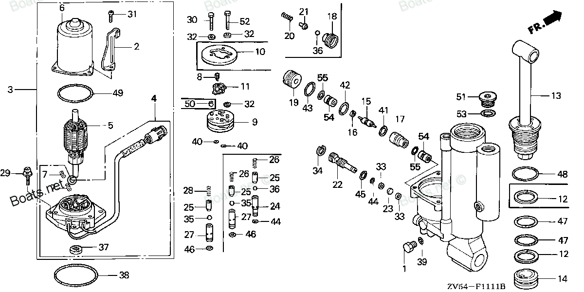
56113-ZV5-821 JOINT, DRIVE (Honda Code 4594495). Honda
BF35AM LRTA, BF35AM XRTA, BF40A1 LHTA, BF40A1 LRTA, BF40A1 XRTA, BF40A2 LHTA, BF40A2 LRTA, BF40A2 XRTA, BF40AW LHTA, BF40AW LRTA, BF40AW XRTA, BF40AX LHTA, BF40AX LRTA, BF40AX XRTA, BF40AY LHTA, BF40AY LRTA, BF40AY XRTA, BF45AM LRTA, BF45AM SRTA, BF4
JOINT
. Honda parts")
Price: query
Rating:
Number on catalog scheme: 8
Compatible models:
BF35AM LRTA
BF35AM XRTA
BF40A1 LHTA
BF40A1 LRTA
BF40A1 XRTA
BF40A2 LHTA
BF40A2 LRTA
BF40A2 XRTA
BF40AW LHTA
BF40AW LRTA
BF40AW XRTA
BF40AX LHTA
BF40AX LRTA
BF40AX XRTA
BF40AY LHTA
BF40AY LRTA
BF40AY XRTA
BF45AM LRTA
BF45AM SRTA
BF45AM XRTA
BF50A1 LHTA
BF50A1 LRTA
BF50A1 XRTA
BF50A2 LHTA
BF50A2 LRTA
BF50A2 XRTA
BF50AW LHTA
BF50AW LRTA
BF50AW XRTA
BF50AX LHTA
BF50AX LRTA
BF50AX XRTA
BF50AY LHTA
BF50AY LRTA
BF50AY XRTA
Honda
Honda entire parts catalog list:
- POWER TILT COMPONENTS » 56113-ZV5-821
- POWER TILT COMPONENTS » 56113-ZV5-821
- POWER TRIM-TILT » 56113-ZV5-821
- POWER TRIM-TILT » 56113-ZV5-821
- POWER TRIM-TILT » 56113-ZV5-821
- POWER TRIM-TILT » 56113-ZV5-821
- POWER TRIM-TILT » 56113-ZV5-821
- POWER TRIM-TILT » 56113-ZV5-821
- POWER TILT COMPONENTS » 56113-ZV5-821
- POWER TILT COMPONENTS » 56113-ZV5-821
- POWER TILT COMPONENTS » 56113-ZV5-821
- POWER TILT COMPONENTS » 56113-ZV5-821
- POWER TILT COMPONENTS » 56113-ZV5-821
- POWER TILT COMPONENTS » 56113-ZV5-821
- POWER TRIM-TILT » 56113-ZV5-821
- POWER TRIM-TILT » 56113-ZV5-821
- POWER TRIM-TILT » 56113-ZV5-821
- POWER TILT COMPONENTS » 56113-ZV5-821
- POWER TILT COMPONENTS » 56113-ZV5-821
- POWER TILT COMPONENTS » 56113-ZV5-821
- POWER TRIM-TILT » 56113-ZV5-821
- POWER TRIM-TILT » 56113-ZV5-821
- POWER TRIM-TILT » 56113-ZV5-821
- POWER TRIM-TILT » 56113-ZV5-821
- POWER TRIM-TILT » 56113-ZV5-821
- POWER TRIM-TILT » 56113-ZV5-821
- POWER TILT COMPONENTS » 56113-ZV5-821
- POWER TILT COMPONENTS » 56113-ZV5-821
- POWER TILT COMPONENTS » 56113-ZV5-821
- POWER TILT COMPONENTS » 56113-ZV5-821
- POWER TILT COMPONENTS » 56113-ZV5-821
- POWER TILT COMPONENTS » 56113-ZV5-821
- POWER TRIM-TILT » 56113-ZV5-821
- POWER TRIM-TILT » 56113-ZV5-821
- POWER TRIM-TILT » 56113-ZV5-821
Information:
Probable Causes
Cold mode operation
Jacket water heater
Air inlet heater
Coolant temperature
Coolant leak
Engine speed/timing sensor
Flash file
Unit injector
Fuel quality
Gear group
Valve lashRecommended Actions
Table 1
Troubleshooting Test Steps Values Results
1. Cold Mode Operation
Cold mode
Excessive white smoke emissions can occur during cold mode operation of the engine. During cold mode operation of the engine, the ECM can modify the injection timing and the ECM can cut out certain engine cylinders. This will increase startability and reduces warm up time. Cold mode is activated whenever the engine coolant temperature falls below a predetermined value. Cold mode remains active until the engine has warmed or a time limit is exceeded.
2. Jacket Water Heater
A. Check for proper operation of the jacket water heater, if applicable.
Heater
Result: The jacket water heater is OK.
Proceed to Test Step 3.
The jacket water heater is NOT OK.
Repair the circuit for the jacket water heater, if necessary.
3. Air Inlet Heater
A. Check for proper operation of the air inlet heater, if applicable.
Heater
Result: The air inlet heater is OK.
Proceed to Test Step 4.
Result: The air inlet heater is NOT OK.
Refer to the particular test procedure for the application.
4. Coolant Temperature
A. Check the coolant temperature.
Temperature
Result: The coolant temperature is reasonable for the conditions that are present.
Proceed to Test Step 5.
Result: The temperature is NOT reasonable for the conditions that are present.
Refer to Systems Operation/Testing and Adjusting, "Water Temperature Regulator - Test"
5. Coolant Leak
A. Check for an internal coolant leak into the cylinder and/or the exhaust.
Inspect the following components for defects that can cause internal coolant leakage:
- Cylinder head
- Cylinder head gasket
- Cylinder liners
- Turbocharger
Leak
Result: There is NOT an internal coolant leak.
Proceed to Test Step 6.
Result: There is an internal coolant leak.
Make the necessary repairs. Verify that the problem is resolved.
6. Engine Speed/Timing Sensor
A. Check the calibration of the engine speed/timing sensors.
Sensors
Result: The engine speed/timing sensors are calibrated correctly.
Proceed to Test Step 7.
Result: The engine speed/timing sensors are NOT calibrated correctly.
Refer to Troubleshooting, "Timing - Calibrate" for more information.
7. Flash File
A. Verify that the latest flash file is installed.
Software
Result: The latest flash file is installed.
Proceed to Test Step 8.
Result: The latest flash file is NOT installed.
Install the latest flash file.
8. Injector
A. Perform the "Cylinder Cutout Test" on Cat ET in order to isolate any cylinders that can be misfiring. A misfiring cylinder could be related to an injector that is worn or not operating properly.
B. Cut out each individual cylinder for 30 to 60 seconds. Verify that the smoke decreases.
Unit Injector
Result: Cat ET does NOT indicate a problem.
Proceed to Test Step 9.
Result: Cat ET indicates a problem.
Remove the electronic unit injector from the suspect cylinder. Refer to Disassembly and Assembly
9. Fuel Quality
A. Obtain a fuel analysis.
Low cetane fuel can create white smoke. If necessary, replace the fuel with a higher cetane fuel.
Fuel
Result: The fuel quality is OK.
Proceed to Test Step 11.
The fuel quality is NOT OK.
Drain the fuel, and replace the fuel.
10. Front Gear Group
A. Verify that the timing of the crankshaft and camshaft drive gears are set with the proper orientation.
Components
Result: The timing of the crankshaft and camshaft are oriented properly.
Proceed to Test Step 11.
Result: The timing of the crankshaft and camshaft are NOT oriented properly.
Make the necessary repairs. Refer to Disassembly and Assembly for information that is related to the correct gear installation.
11. Valve Lash
A. Check the valve lash.
Valve lash
Result: The valve lash is within specification.
Result: The valve lash is NOT within specification.
Set the valve lash to the correct specifications. Refer to Systems Operation/Testing and Adjusting, "Engine Valve Lash - Inspect/Adjust"
Parts joint Honda:
19271-ZV1-810

19271-ZV1-810 JOINT, WATER HOSE (Honda Code 2149847).
BF15A1 LA, BF15A1 LAS, BF15A1 SA, BF15A1 SAS, BF15A1 XAS, BF15A2 LA, BF15A2 LAS, BF15A2 SA, BF15A2 SAS, BF15A2 XAS, BF15AM LA, BF15AM LAS, BF15AM SA, BF15AM SAS, BF15AM XAS, BF15AW LA, BF15AW LAS, BF15AW SA, BF15AW SAS, BF15AW XAS, BF15AX LA, BF15AX
19271-ZV5-000

19271-ZV5-000 JOINT, WATER HOSE (Honda Code 3702602).
BF25A1 LHA, BF25A1 LHSA, BF25A1 LRSA, BF25A1 SHA, BF25A1 SHSA, BF25A1 SRSA, BF25A1 XRSA, BF25A2 LHA, BF25A2 LHSA, BF25A2 LRSA, BF25A2 SHA, BF25A2 SHSA, BF25A2 SRSA, BF25A2 XRSA, BF25A3 LHA, BF25A3 LHSA, BF25A3 LRSA, BF25A3 SHA, BF25A3 SHSA, BF25A3 SR
16900-ZV5-901

16900-ZV5-901 JOINT ASSY., FUEL (Honda Code 4731238).
BF115A1 LA, BF115A1 LCA, BF115A1 XA, BF115A1 XCA, BF115A2 LA, BF115A2 LCA, BF115A2 XA, BF115A2 XCA, BF115A3 LA, BF115A3 LCA, BF115A3 XA, BF115A3 XCA, BF115AX LA, BF115AX LCA, BF115AX XA, BF115AX XCA, BF115AY LA, BF115AY LCA, BF115AY XA, BF115AY XCA,
24312-ZV5-000
24312-ZV5-000 JOINT, SHIFT ROD (Honda Code 3702859).
BF35AM LHA, BF35AM LRA, BF35AM LRTA, BF35AM SHA, BF35AM XRTA, BF40A1 LHA, BF40A1 LHTA, BF40A1 LRA, BF40A1 LRTA, BF40A1 XRTA, BF40A2 LHA, BF40A2 LHTA, BF40A2 LRA, BF40A2 LRTA, BF40A2 XRTA, BF40A3 LHA, BF40A3 LHTA, BF40A3 LRA, BF40A3 LRTA, BF40A3 XRTA,
06190-ZV1-860

06190-ZV1-860 JOINT KIT, WATER HOSE (Honda Code 2944239).
BF15D3 LGA, BF15D3 LHA, BF15D3 LHGA, BF15D3 LHSA, BF15D3 LHTA, BF15D3 LRA, BF15D3 LRTA, BF15D3 SHA, BF15D3 SHGA, BF15D3 SHSA, BF15D3 SHTA, BF15D3 SRTA, BF15D3 XHA, BF15D3 XHGA, BF15D4 LGA, BF15D4 LHA, BF15D4 LHGA, BF15D4 LHSA, BF15D4 LHTA, BF15D4 LRA
16263-ZA0-000
16263-ZA0-000 JOINT, ROD (Honda Code 1307677).
BF25A1 LHA, BF25A1 LHSA, BF25A1 LRSA, BF25A1 SHA, BF25A1 SHSA, BF25A1 SRSA, BF25A1 XRSA, BF25A2 LHA, BF25A2 LHSA, BF25A2 LRSA, BF25A2 SHA, BF25A2 SHSA, BF25A2 SRSA, BF25A2 XRSA, BF25A3 LHA, BF25A3 LHSA, BF25A3 LRSA, BF25A3 SHA, BF25A3 SHSA, BF25A3 SR
56113-766-801
56113-766-801 JOINT, DRIVE (Honda Code 7226178).
BF25D4 LHTA, BF25D4 LRTA, BF25D4 SRTA, BF25D5 LHTA, BF25D5 LRTA, BF25D5 SRTA, BF25D6 LHTA, BF25D6 LRTA, BF25D6 SRTA, BF25DK0 LRTA, BF25DK2 LRTA, BF25DK3 LRTA, BF30D4 LHTA, BF30D4 LRTA, BF30D4 SRTA, BF30D5 LHTA, BF30D5 LRTA, BF30D5 SRTA, BF30D6 LHTA,