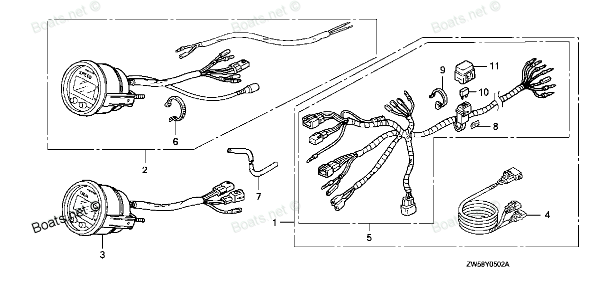
06375-ZY3-810 METER KIT, TACHO (DIGITAL) (Honda Code 7632847). (USE FOR 32540-ZY3-800/801) Honda
BF115A4 LA, BF115A4 XA, BF115A5 LA, BF115A5 LCA, BF115A5 XA, BF115A5 XCA, BF115A6 LA, BF115A6 LCA, BF115A6 XA, BF115A6 XCA, BF130A4 LA, BF130A4 LCA, BF130A4 XA, BF130A4 XCA, BF200A4 LA, BF200A4 XA, BF200A4 XCA, BF200A4 XXA, BF200A4 XXCA, BF200A5 LA,
METER
 (Honda Code 7632847). (USE FOR 32540-ZY3-800/801) Honda parts")
Price: query
Rating:
Number on catalog scheme: 3
Compatible models:
BF115A4 LA
BF115A4 XA
BF115A5 LA
BF115A5 LCA
BF115A5 XA
BF115A5 XCA
BF115A6 LA
BF115A6 LCA
BF115A6 XA
BF115A6 XCA
BF130A4 LA
BF130A4 LCA
BF130A4 XA
BF130A4 XCA
BF200A4 LA
BF200A4 XA
BF200A4 XCA
BF200A4 XXA
BF200A4 XXCA
BF200A5 LA
BF200A5 XA
BF200A5 XCA
BF200A5 XXA
BF200A5 XXCA
BF225A4 LA
BF225A4 XA
BF225A4 XCA
BF225A4 XXA
BF225A4 XXCA
BF225A5 LA
BF225A5 XA
BF225A5 XCA
BF225A5 XXA
BF225A5 XXCA
Honda
Honda entire parts catalog list:
- METER (DIGITAL) » 06375-ZY3-810
- METER (DIGITAL) » 06375-ZY3-810
- METER (DIGITAL) » 06375-ZY3-810
- METER (DIGITAL) » 06375-ZY3-810
- METER (DIGITAL) » 06375-ZY3-810
- METER (DIGITAL) » 06375-ZY3-810
- METER (DIGITAL) » 06375-ZY3-810
- METER (DIGITAL) » 06375-ZY3-810
- METER (DIGITAL) » 06375-ZY3-810
- METER (DIGITAL) » 06375-ZY3-810
- METER (DIGITAL) » 06375-ZY3-810
- METER (DIGITAL) » 06375-ZY3-810
- METER (DIGITAL) » 06375-ZY3-810
- METER (DIGITAL) » 06375-ZY3-810
- METER (2) » 06375-ZY3-810
- METER (2) » 06375-ZY3-810
- METER (2) » 06375-ZY3-810
- METER (2) » 06375-ZY3-810
- METER (2) » 06375-ZY3-810
- METER (2) » 06375-ZY3-810
- METER (2) » 06375-ZY3-810
- METER (2) » 06375-ZY3-810
- METER (2) » 06375-ZY3-810
- METER (2) » 06375-ZY3-810
- METER (2) » 06375-ZY3-810
- METER (2) » 06375-ZY3-810
- METER (2) » 06375-ZY3-810
- METER (2) » 06375-ZY3-810
- METER (2) » 06375-ZY3-810
- METER (2) » 06375-ZY3-810
- METER (2) » 06375-ZY3-810
- METER (2) » 06375-ZY3-810
- METER (2) » 06375-ZY3-810
- METER (2) » 06375-ZY3-810
Information:
ENGINE OIL AND OIL FILTER
1. Engine oil specifications Use oils that meet the Engine Service Classification CC.2 Oil level check(1) Check the crankcase oil level with a dipstick with the engine kept level.(2) If the oil level is at or below "L" (low level) mark on the dipstick, add oil to "H" (high level) mark on the dipstick. a) After adding oil, leave the engine standing for one minute and check the oil level.b) Avoid mixing different brands of oils. In some cases, they are not compatible with each other and deteriorate when mixed. Use the same brand at successive intervals. c) If the engine has been left standing for a long period of time, check the oil for level and contamination before starting the engine. Start and run the engine for a few minutes. Then stop the engine and check the oil level again.Recommended engine oil viscosities
Checking oil level3. Oil change (1) Change the oil after the first 50 service hours of operation of a new or reconditioned engine and every 100 service hours thereafter.(2) Warm up the engine. Remove the drain plug and allow the oil to drain in a container. Install the drain plug, tightening it to the specified torque, and refill the engine with new oil.(3) Refill to the "H" mark on the dipstick. Approximately 0.5 liter (0.5 qt) of oil is required for the oil filter and oil lines. 4. Oil filter change
Removing used oil filter(1) Change the oil filter every 100 service hours.(2) Remove the used filter with a filter wrench. Discard the filter. (3) Remove all of the old filter gasket from the filter base and apply a thin coat of engine oil to the gasket on the new filter. Install the filter by hand until its gasket contacts the base. Tighten 3/4 turn more.
Do not cause damage to the O-ring when installing the filter.
(4) Add 0.5 liter (0.5 qt) of oil.(5) Start the engine and check for leaks around the filter. (6) Stop the engine. Check the oil level and add oil if necessary.
Installing new oil filterVALVE CLEARANCE
Make an adjustment to the valve clearance when the engine is cold.(1) Slightly loosen the cylinder head bolts and retighten them to the specified torque in number sequence.
Cylinder head bolt tightening sequence(2) Find top dead center compression position for No. 1 piston by using the procedure that follows: (a) Turn the crankshaft until TDC mark on the crankshaft pulley is aligned with the mark on the timing gear case. (b) With No. 1 piston at top dead center on the compression stroke, the rocker arms will not be moved when the crankshaft is turned approximately 20° in both directions. (c) If the rocker arms move, No. 1 piston is at top dead center on the intake or exhaust stroke. In such a case, turn the crankshaft 360° in the direction of engine rotation again. No. 1 piston is now at top dead center on the compression stroke. (3) Loosen the lock nut for the adjusting screw. With a feeler gauge inserted between the rocker arm and valve cap, adjust the valve clearance by turning the adjusting screw.
Unit: mm (in.)
Timing mark(4) Hold the adjusting screw and tighten the lock nut.(5) After the valve clearance on the valves for No. 1 cylinder has been adjusted, turn the crankshaft 180° in the direction of engine rotation and adjust the valve clearance on the valves for the remainder of the cylinders in firing order (injection sequence)
After the valve clearance on the valves for all cylinders has been adjusted, turn the crankshaft two or three times and make sure the valve clearance is correct.
Adjusting valve clearanceFUEL INJECTION TIMING
1. Preparation(1) Close the fuel filter valve.(2) Disconnect the No. 1 fuel injection pipe from the cylinder head and injection pump.(3) Remove No. 1 delivery valve holder from the injection pump. Remove the delivery valve and spring from the holder. Restore the delivery valve holder only to the injection pump.(4) Connect the fuel injection pipe to the injection pump.(5) Hold the speed control lever in the low speed position.
Removing delivery valve and spring2. Inspection2.1 Fuel flow method(1) Open the fuel filter valve. Turn the starter switch key to ON position. Fuel will come from the injection pipe with high pressure when the starter switch key is turned to ON position if the engine is equipped with an electric fuel pump. Direct fuel flow into the container.(2) Slowly turn the crankshaft clockwise, looking at the free end of the injection pipe. The instant fuel stops coming out is the fuel injection timing. Turn the crankshaft in reverse direction just a little and do Step (2) again to verify the injection timing.
Fuel coming from injection pipe
Fuel stops coming from injection pipe(3) The fuel injection timing is correct if IT mark on the crankshaft pulley is aligned with the mark on the timing gear case when fuel stops from the injection pipe.
Timing mark2.2 Alternate method In the fuel flow method, the delivery valve has to be removed. As a result, there is a good chance for dirt particles to get inside the fuel injection pump. In this alternate method, however, it is not necessary to remove the delivery valve. (1) Disconnect No. 1 fuel injection pipe at the fuel injection nozzle (cylinder head).(2) Prime the fuel system.(3) Slowly turn the crankshaft clockwise until fuel just swells at the free end of the injection pipe and, at that instant, check the position of the IT mark with respect to the mark on the gear case. This timing is approximately 1° retarded. Take this 1° retardation into account when making a shim adjustment.
Disconnecting No. 1 fuel injection pipe
Timing mark3. Adjustment(1) If the fuel injection timing is incorrect, change the thickness of shims under the fuel injection pump. An increase or decrease of the shims by 0.1 mm (0.004 in.) will vary the timing by 1°.(2) Increase the thickness of the shims to retard the timing or decrease it to advance the timing. Four kinds of shims
Parts meter Honda:
37450-ZV5-911
37450-ZV5-911 METER ASSY., VOLT (Honda Code 3637279). (NOT AVAILABLE)
BF115A1 LA, BF115A1 LCA, BF115A1 XA, BF115A1 XCA, BF115A2 LA, BF115A2 LCA, BF115A2 XA, BF115A2 XCA, BF115A3 LA, BF115A3 LCA, BF115A3 XA, BF115A3 XCA, BF115A4 LA, BF115A4 LCA, BF115A4 XA, BF115A4 XCA, BF115A5 LA, BF115A5 LCA, BF115A5 XA, BF115A5 XCA,
39700-ZV5-800AH
39700-ZV5-800AH METER ASSY., HOUR L.C.D. (Honda Code 4210654).
BF115A1 LA, BF115A1 LCA, BF115A1 XA, BF115A1 XCA, BF115A2 LA, BF115A2 LCA, BF115A2 XA, BF115A2 XCA, BF115A3 LA, BF115A3 LCA, BF115A3 XA, BF115A3 XCA, BF115A4 LA, BF115A4 LCA, BF115A4 XA, BF115A4 XCA, BF115A5 LA, BF115A5 LCA, BF115A5 XA, BF115A5 XCA,
06373-ZW5-U10
06373-ZW5-U10 METER KIT, SPEED *NH1D* (B) (Honda Code 6796312). (BLACK)
BF115A1 LA, BF115A1 LCA, BF115A1 XA, BF115A1 XCA, BF115A2 LA, BF115A2 LCA, BF115A2 XA, BF115A2 XCA, BF115A3 LA, BF115A3 LCA, BF115A3 XA, BF115A3 XCA, BF115A4 LA, BF115A4 LCA, BF115A4 XA, BF115A4 XCA, BF130A1 LA, BF130A1 LCA, BF130A1 XA, BF130A1 XCA,
06373-ZW5-U00
06373-ZW5-U00 METER KIT, SPEED (Honda Code 6796304).
BF115A1 LA, BF115A1 LCA, BF115A1 XA, BF115A1 XCA, BF115A2 LA, BF115A2 LCA, BF115A2 XA, BF115A2 XCA, BF115A3 LA, BF115A3 LCA, BF115A3 XA, BF115A3 XCA, BF115A4 LA, BF115A4 LCA, BF115A4 XA, BF115A4 XCA, BF130A1 LA, BF130A1 LCA, BF130A1 XA, BF130A1 XCA,
06374-ZW5-U00
06374-ZW5-U00 METER KIT, VOLT (Honda Code 6796320).
BF115A1 LA, BF115A1 LCA, BF115A1 XA, BF115A1 XCA, BF115A2 LA, BF115A2 LCA, BF115A2 XA, BF115A2 XCA, BF115A3 LA, BF115A3 LCA, BF115A3 XA, BF115A3 XCA, BF115A4 LA, BF115A4 LCA, BF115A4 XA, BF115A4 XCA, BF115A5 LA, BF115A5 LCA, BF115A5 XA, BF115A5 XCA,
06374-ZW5-U10
06374-ZW5-U10 METER KIT, VOLT *NH1D* (B) (Honda Code 6796338). (BLACK)
BF115A1 LA, BF115A1 LCA, BF115A1 XA, BF115A1 XCA, BF115A2 LA, BF115A2 LCA, BF115A2 XA, BF115A2 XCA, BF115A3 LA, BF115A3 LCA, BF115A3 XA, BF115A3 XCA, BF115A4 LA, BF115A4 LCA, BF115A4 XA, BF115A4 XCA, BF115A5 LA, BF115A5 LCA, BF115A5 XA, BF115A5 XCA,
06375-ZW5-U00
06375-ZW5-U00 METER KIT, TACHO (Honda Code 6796387).
BF115A1 LA, BF115A1 LCA, BF115A1 XA, BF115A1 XCA, BF115A2 LA, BF115A2 LCA, BF115A2 XA, BF115A2 XCA, BF115A3 LA, BF115A3 LCA, BF115A3 XA, BF115A3 XCA, BF115A4 LA, BF115A4 LCA, BF115A4 XA, BF115A4 XCA, BF115A5 LA, BF115A5 LCA, BF115A5 XA, BF115A5 XCA,
06375-ZW5-U01
06375-ZW5-U01 METER KIT, TACHO (Honda Code 8572612).
BF115A1 LA, BF115A1 LCA, BF115A1 XA, BF115A1 XCA, BF115A2 LA, BF115A2 LCA, BF115A2 XA, BF115A2 XCA, BF115A3 LA, BF115A3 LCA, BF115A3 XA, BF115A3 XCA, BF115A4 LA, BF115A4 LCA, BF115A4 XA, BF115A4 XCA, BF115A5 LA, BF115A5 LCA, BF115A5 XA, BF115A5 XCA,