36120-ZW4-H12 MOTOR ASSY., POWER TILT (Honda Code 8262438). Honda
BF40A4 LHTA, BF40A4 LRTA, BF40A5 LHTA, BF40A5 LRTA, BF40A6 LHTA, BF40A6 LRTA, BF40AK0 LRTA, BF40DK2 LRTA, BF50A4 LHTA, BF50A4 LRTA, BF50A4 SRJA, BF50A4 XRTA, BF50A5 LHTA, BF50A5 LRTA, BF50A5 SRJA, BF50A5 XRTA, BF50A6 LHTA, BF50A6 LRTA, BF50A6 SRJA, B
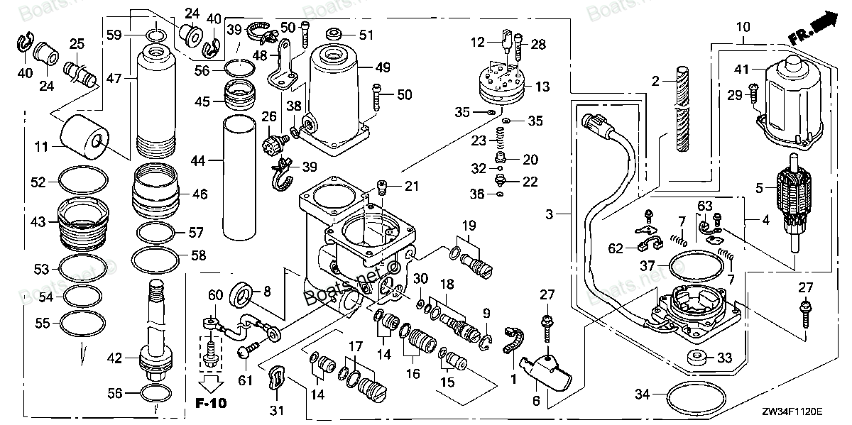
MOTOR
. Honda parts")
Price: query
Rating:
You can buy parts:
As an associate, we earn commssions on qualifying purchases through the links below

Replacement for fits Power Tilt Trim Motor for Outboard BF40 BF50 Engines 2004-UP 36120-Zw4-H12
FZCXHONJ
FZCXHONJ

Motorcycle Repair Parts 430-22111 430-22158 Tilt Trim Motor for Honda for Outboard BF40 BF50 Engines 2004-UP 36120-ZW4-H12
ZLLBMMD Good texture and have long service life. || To ensure the practicality and durability. || Small and exquisite appearance, with beautiful design. || Convenient to use and with good performance. || Great workmanship, perfect replacement for the old or damaged. || Easy installation, a direct replacement for the damaged and broken parts.
ZLLBMMD Good texture and have long service life. || To ensure the practicality and durability. || Small and exquisite appearance, with beautiful design. || Convenient to use and with good performance. || Great workmanship, perfect replacement for the old or damaged. || Easy installation, a direct replacement for the damaged and broken parts.

430-22111 430-22158 Tilt Trim Motor,Compatible With Outboard BF40 BF50 Engines 2004-UP 36120-ZW4-H12
CXOTKADS Compatibility:1:1 perfect match, easy to replace with old motor. || Strong power: The starter motor assembly can start instantly even in cold weather or low battery, so say goodbye to sluggish starting. || Convenient installation: The starter motor assembly can be installed by non-professionals, saving time and money. || Quiet operation: motorcycle starter motor assembly gear structure optimization, ultra-low operating noise, creating a quiet and comfortable starting experience. || 430-22111 430-22158 Tilt Trim Motor ,Compatible With Outboard BF40 BF50 Engines 2004-UP 36120-ZW4-H12
CXOTKADS Compatibility:1:1 perfect match, easy to replace with old motor. || Strong power: The starter motor assembly can start instantly even in cold weather or low battery, so say goodbye to sluggish starting. || Convenient installation: The starter motor assembly can be installed by non-professionals, saving time and money. || Quiet operation: motorcycle starter motor assembly gear structure optimization, ultra-low operating noise, creating a quiet and comfortable starting experience. || 430-22111 430-22158 Tilt Trim Motor ,Compatible With Outboard BF40 BF50 Engines 2004-UP 36120-ZW4-H12
Number on catalog scheme: 3
Compatible models:
BF40A4 LHTA
BF40A4 LRTA
BF40A5 LHTA
BF40A5 LRTA
BF40A6 LHTA
BF40A6 LRTA
BF40AK0 LRTA
BF40DK2 LRTA
BF50A4 LHTA
BF50A4 LRTA
BF50A4 SRJA
BF50A4 XRTA
BF50A5 LHTA
BF50A5 LRTA
BF50A5 SRJA
BF50A5 XRTA
BF50A6 LHTA
BF50A6 LRTA
BF50A6 SRJA
BF50A6 XRTA
BF50AK0 LRTA
BF50AK0 SRJA
BF50AK0 XRTA
BF50DK2 LRTA
BF50DK2 XRTA
Honda
Honda entire parts catalog list:
- POWER TRIM-TILT » 36120-ZW4-H12
- POWER TRIM-TILT » 36120-ZW4-H12
- POWER TRIM-TILT » 36120-ZW4-H12
- POWER TRIM-TILT » 36120-ZW4-H12
- POWER TRIM-TILT » 36120-ZW4-H12
- POWER TRIM-TILT » 36120-ZW4-H12
- POWER TRIM-TILT » 36120-ZW4-H12
- POWER TRIM-TILT » 36120-ZW4-H12
- POWER TRIM-TILT » 36120-ZW4-H12
- POWER TRIM-TILT » 36120-ZW4-H12
- POWER TRIM-TILT » 36120-ZW4-H12
- POWER TRIM-TILT » 36120-ZW4-H12
- POWER TRIM-TILT » 36120-ZW4-H12
- POWER TRIM-TILT » 36120-ZW4-H12
- POWER TRIM-TILT » 36120-ZW4-H12
- POWER TRIM-TILT » 36120-ZW4-H12
- POWER TRIM-TILT » 36120-ZW4-H12
- POWER TRIM-TILT » 36120-ZW4-H12
- POWER TRIM-TILT » 36120-ZW4-H12
- POWER TRIM-TILT » 36120-ZW4-H12
- POWER TRIM-TILT » 36120-ZW4-H12
- POWER TRIM-TILT » 36120-ZW4-H12
- POWER TRIM-TILT » 36120-ZW4-H12
- POWER TRIM-TILT » 36120-ZW4-H12
- POWER TRIM-TILT » 36120-ZW4-H12
Information:
start by: a) remove governor from fuel injection pump housing1. Remove the fuel injection pumps as follows: a) Remove the protection cap from the fuel injection pump. b) Install tool (A) and loosen bushing (1). c) Install tool (B) through tool (A) and on to the bonnet (2).d) Push down on tool (B) and remove tool (A) and the bushing from the housing.e) Remove the seal and lift the fuel injection pump out of the housing. Put identification on each pump as to its location in the housing.
During disassembly and assembly of the fuel injection pumps, be extra careful not to cause damage to the finished surfaces of the plungers and barrels. The plunger and barrel are precision parts and can not be mixed with those of another pump.
2. Disassemble the fuel injection pumps as follows: a) Remove ring (5), bonnet (2), spring (3), and check valve (4) from the barrel.b) Remove plunger (9), washer (8), and spring (7) from barrel (6). 3. Remove rack (11) and spring (10) from the housing.4. Remove the lifters from the housing with a magnet. Put identification on each lifter as to its location in the housing. 5. Remove bolt (12) and the lock. Remove plate (13) and gear (15).6. Remove the bolts, lock, and plate (14) from the housing. 7. Remove camshaft (16). 8. Remove the camshaft bearings from the housing with tool group (C).Assemble Fuel Injection Pump Housing
1. Install the bearings for the camshaft in the housing with tool group (A). After installation of the bearings, line bore the front and rear bearings as shown in SPECIAL INSTRUCTION FORM NO. GMG00672. 2. Put clean engine oil on the camshaft. Install camshaft (1) in the housing. 3. Put camshaft plate (2) in position and install the bolts and lock. 4. Install gear (5) on the camshaft. Install plate (4), lock, and bolt (3).5. Install the lifters in the same location from which they were removed. 6. Put clean fuel oil on the rack. Install rack (7) with the groove (slot) toward the front of the housing. Install spring (6) on the rack. If new lifters and pumps are to be installed, the timing dimension must be set. See FUEL PUMP TIMING DIMENSION SETTING - OFF ENGINE in TESTING AND ADJUSTING. 7. Remove cover (8). Move the rack toward the governor end of the housing until the groove (slot) in the rack is beyond the centering hole. Install tool (B) in the hole. Move the rack toward the front of the housing until the slot in the rack is against tool (B). The rack is now in center position.8. Assemble the fuel injection pumps as follows: a) Put clean fuel on all of the parts.b) Install the spring, washer, and plunger in the barrel.c) Install the spring, check valve, bonnet, and ring on the barrel.
Do not put the fuel injection pumps into the housing until the rack has been put in center position.
9. With the rack in center position, install the fuel injection pumps as follows: a) Turn the camshaft until the lobe under the pump being installed is away from the pump. b) Install tool (C) on the pump.c) Put the notches in the bonnet and barrel in alignment with the center tooth on gear (9).d) Put the pump in position in the housing in the same location from which it was removed so that the notches in the barrel and bonnet are in alignment with the dowels in the housing, and the center tooth on the gear is in alignment with the center notch on the rack.e) Install the seal and bushing. Push down on tool (C) and tighten the bushing by hand until the threads on the bushing are even with the top of the housing. If the bushing can not be tightened this far, remove it. Remove the pump. Put the notches in alignment and install it again.
Do not use force to install the bushings. If the pump is installed correctly, the bushing can be tightened by hand until the threads on the bushing are even with the top of the housing.
f) After each pump has been installed, check the rack movement as follows: Install tooling (D) on the housing. Remove timing pin (B) and check the total rack movement. The total rack movement must be approximately .624 in. (15.85 mm). If the total movement is not correct, remove the pump, put the components in alignment again, and install the pump again. A pump that is installed one tooth off will cause a decrease in total rack movement of approximately .100 in. (2.54 mm).g) After each pump is installed correctly, remove tool (C). Tighten the bushings to a torque of 100 10 lb.ft. (13.8 1.4 mkg) with tool (E). Install the protection caps on the pumps.10. After the fuel injection pump housing and governor has been installed on the engine, make an adjustment to the governor and rack. See GOVERNOR ADJUSTMENTS and FUEL RACK SETTING in TESTING AND ADJUSTING.end by:a) install governor on fuel injection pump housing