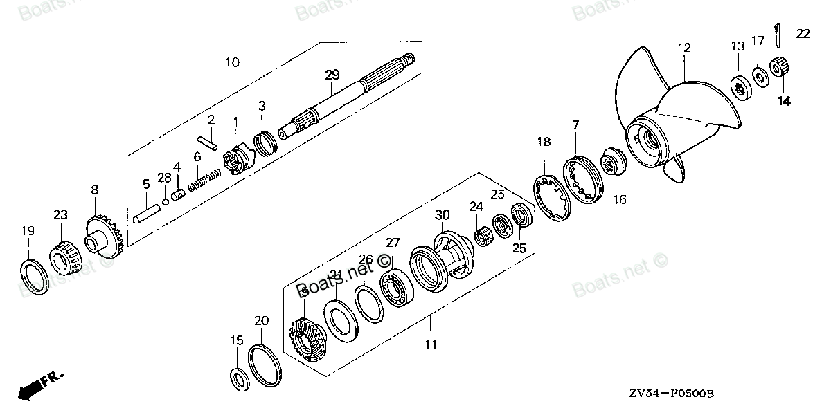
24102-ZV5-000 PIN, SHIFTER (6.3X33) (Honda Code 3702784). Honda
BF35AM LHA, BF35AM LRA, BF35AM LRTA, BF35AM SHA, BF35AM XRTA, BF40A1 LHA, BF40A1 LHTA, BF40A1 LRA, BF40A1 LRTA, BF40A1 XRTA, BF40A2 LHA, BF40A2 LHTA, BF40A2 LRA, BF40A2 LRTA, BF40A2 XRTA, BF40A3 LHA, BF40A3 LHTA, BF40A3 LRA, BF40A3 LRTA, BF40A3 XRTA,
PIN
 (Honda Code 3702784). Honda parts")
Price: query
Rating:
Number on catalog scheme: 2
Compatible models:
BF35AM LHA
BF35AM LRA
BF35AM LRTA
BF35AM SHA
BF35AM XRTA
BF40A1 LHA
BF40A1 LHTA
BF40A1 LRA
BF40A1 LRTA
BF40A1 XRTA
BF40A2 LHA
BF40A2 LHTA
BF40A2 LRA
BF40A2 LRTA
BF40A2 XRTA
BF40A3 LHA
BF40A3 LHTA
BF40A3 LRA
BF40A3 LRTA
BF40A3 XRTA
BF40A4 LHA
BF40A4 LHTA
BF40A4 LRTA
BF40A5 LHA
BF40A5 LHTA
BF40A5 LRTA
BF40A6 LHA
BF40A6 LHTA
BF40A6 LRTA
BF40AK0 LHA
BF40AK0 LRTA
BF40AW LHA
BF40AW LHTA
BF40AW LRA
BF40AW LRTA
BF40AW XRTA
BF40AX LHA
BF40AX LHTA
BF40AX LRA
BF40AX LRTA
BF40AX XRTA
BF40AY LHA
BF40AY LHTA
BF40AY LRA
BF40AY LRTA
BF40AY XRTA
BF40DK2 LHA
BF40DK2 LRTA
BF45AM LHA
BF45AM LRA
BF45AM LRTA
BF45AM SRTA
BF45AM XRTA
BF50A1 LHTA
BF50A1 LRA
BF50A1 LRTA
BF50A1 XRTA
BF50A2 LHTA
BF50A2 LRA
BF50A2 LRTA
BF50A2 XRTA
BF50A3 LHTA
BF50A3 LRA
BF50A3 LRTA
BF50A3 XRTA
BF50A4 LHTA
BF50A4 LRTA
BF50A4 XRTA
BF50A5 LHTA
BF50A5 LRTA
BF50A5 XRTA
BF50A6 LHTA
BF50A6 LRTA
BF50A6 XRTA
BF50AK0 LRTA
BF50AK0 XRTA
BF50AW LHTA
BF50AW LRA
BF50AW LRTA
BF50AW XRTA
BF50AX LHTA
BF50AX LRA
BF50AX LRTA
BF50AX XRTA
BF50AY LHTA
BF50AY LRA
BF50AY LRTA
BF50AY XRTA
BF50DK2 LRTA
BF50DK2 XRTA
BF60AK1 LRTA
BF60AK1 XRTA
Honda
Honda entire parts catalog list:
- PROPELLER » 24102-ZV5-000
- PROPELLER » 24102-ZV5-000
- PROPELLER » 24102-ZV5-000
- PROPELLER » 24102-ZV5-000
- PROPELLER » 24102-ZV5-000
- PROPELLER » 24102-ZV5-000
- PROPELLER » 24102-ZV5-000
- PROPELLER » 24102-ZV5-000
- PROPELLER » 24102-ZV5-000
- PROPELLER » 24102-ZV5-000
- PROPELLER » 24102-ZV5-000
- PROPELLER » 24102-ZV5-000
- PROPELLER » 24102-ZV5-000
- PROPELLER » 24102-ZV5-000
- PROPELLER » 24102-ZV5-000
- PROPELLER » 24102-ZV5-000
- PROPELLER » 24102-ZV5-000
- PROPELLER » 24102-ZV5-000
- PROPELLER » 24102-ZV5-000
- PROPELLER » 24102-ZV5-000
- PROPELLER PROPELLER SHAFT » 24102-ZV5-000
- PROPELLER PROPELLER SHAFT » 24102-ZV5-000
- PROPELLER PROPELLER SHAFT » 24102-ZV5-000
- PROPELLER PROPELLER SHAFT » 24102-ZV5-000
- PROPELLER PROPELLER SHAFT » 24102-ZV5-000
- PROPELLER PROPELLER SHAFT » 24102-ZV5-000
- PROPELLER PROPELLER SHAFT » 24102-ZV5-000
- PROPELLER PROPELLER SHAFT » 24102-ZV5-000
- PROPELLER PROPELLER SHAFT » 24102-ZV5-000
- PROPELLER PROPELLER SHAFT » 24102-ZV5-000
- PROPELLER PROPELLER SHAFT » 24102-ZV5-000
- PROPELLER » 24102-ZV5-000
- PROPELLER » 24102-ZV5-000
- PROPELLER » 24102-ZV5-000
- PROPELLER » 24102-ZV5-000
- PROPELLER » 24102-ZV5-000
- PROPELLER » 24102-ZV5-000
- PROPELLER » 24102-ZV5-000
- PROPELLER » 24102-ZV5-000
- PROPELLER » 24102-ZV5-000
- PROPELLER » 24102-ZV5-000
- PROPELLER » 24102-ZV5-000
- PROPELLER » 24102-ZV5-000
- PROPELLER » 24102-ZV5-000
- PROPELLER » 24102-ZV5-000
- PROPELLER » 24102-ZV5-000
- PROPELLER SHAFT » 24102-ZV5-000
- PROPELLER SHAFT » 24102-ZV5-000
- PROPELLER » 24102-ZV5-000
- PROPELLER » 24102-ZV5-000
- PROPELLER » 24102-ZV5-000
- PROPELLER » 24102-ZV5-000
- PROPELLER » 24102-ZV5-000
- PROPELLER » 24102-ZV5-000
- PROPELLER » 24102-ZV5-000
- PROPELLER » 24102-ZV5-000
- PROPELLER » 24102-ZV5-000
- PROPELLER » 24102-ZV5-000
- PROPELLER » 24102-ZV5-000
- PROPELLER » 24102-ZV5-000
- PROPELLER » 24102-ZV5-000
- PROPELLER » 24102-ZV5-000
- PROPELLER » 24102-ZV5-000
- PROPELLER » 24102-ZV5-000
- PROPELLER » 24102-ZV5-000
- PROPELLER PROPELLER SHAFT » 24102-ZV5-000
- PROPELLER PROPELLER SHAFT » 24102-ZV5-000
- PROPELLER PROPELLER SHAFT » 24102-ZV5-000
- PROPELLER PROPELLER SHAFT » 24102-ZV5-000
- PROPELLER PROPELLER SHAFT » 24102-ZV5-000
- PROPELLER PROPELLER SHAFT » 24102-ZV5-000
- PROPELLER PROPELLER SHAFT » 24102-ZV5-000
- PROPELLER PROPELLER SHAFT » 24102-ZV5-000
- PROPELLER PROPELLER SHAFT » 24102-ZV5-000
- PROPELLER PROPELLER SHAFT » 24102-ZV5-000
- PROPELLER PROPELLER SHAFT » 24102-ZV5-000
- PROPELLER » 24102-ZV5-000
- PROPELLER » 24102-ZV5-000
- PROPELLER » 24102-ZV5-000
- PROPELLER » 24102-ZV5-000
- PROPELLER » 24102-ZV5-000
- PROPELLER » 24102-ZV5-000
- PROPELLER » 24102-ZV5-000
- PROPELLER » 24102-ZV5-000
- PROPELLER » 24102-ZV5-000
- PROPELLER » 24102-ZV5-000
- PROPELLER » 24102-ZV5-000
- PROPELLER » 24102-ZV5-000
- PROPELLER SHAFT » 24102-ZV5-000
- PROPELLER SHAFT » 24102-ZV5-000
- PROPELLER SHAFT (1) » 24102-ZV5-000
- PROPELLER SHAFT (1) » 24102-ZV5-000
Information:
The ends of the bellows are very sharp. Injury could occur if the bellows are not handled properly. Handle the bellows by the convolutions.
The bellows must be supported at all times when the bellows are not installed in the application. Failure to support the bellows adequately could result in the failure of the bellows. Do not use power tools in order to disassemble or assemble any part of the flexible exhaust system.The alignment of the bellows is important. Incorrect alignment may lead to premature failure of the bellows. Misalignment can be identified by visually inspecting the uniformity of the spacing between the convolutions on the bellows.Inspect the bellows for damage prior to installation. If there is any damage to the convolutions, discard the bellows. If there is any difficulty in installation after the repair, discard the bellows.
Illustration 1 g02354623
Typical example
The lateral alignment of the bellows is critical. All the components must be assembled in the same alignment as prior to disassembly. The components that require correct lateral alignment are shown at Positions (A, B, and C).
Illustration 2 g02354616
Typical example
Follow Steps 2.a through Step 2.d in order to remove the flexible exhaust as an assembly from the Clean Emission Module (CEM) and the turbocharger.
Use suitable material in order to encase flexible exhaust pipe (3). Encasing the flexible exhaust pipe will prevent damage of the bellows. Encase bellows for the flexible exhaust pipe (3) between Position (D) and Position (E). Use cable straps in order to retain the suitable material. Note: Ensure that the flexible exhaust pipe is supported at all times.
Loosen ball clamp (2) from the flexible exhaust pipe assembly.
Loosen the bolt for V-band clamp (4). Note: If V-band clamp (4) remain tight on the flanges, apply releasing fluid on the V-band clamp. Lightly tap the bolt on the V-band clamp with a soft faced hammer in order to assist removal. Do not use a prybar in order to remove V-band clamp.
Remove the assembly of the flexible exhaust pipe from the CEM (1) and the turbocharger (5). Note: Ensure that the assembly of the flexible exhaust pipe is supported as the clamps are removed.Disassembly Procedure for the Flexible Exhaust Pipe Assembly
If any part of the flexible exhaust pipe assembly is damaged. Refer to Special Instruction, REHS5014, "Reuse Guideline for the Flexible Exhaust Pipe Group on Tier 4 Engines" for more information.
Illustration 3 g02469602
Typical example
If necessary, follow Step 2.a through Step 2.d in order to disassemble the flexible exhaust pipe assembly.
Make temporary marks in Position (F) on all components of bellows (3) and tube assembly (6) in order to show correct orientation and alignment. Note: Do not scribe the components in order to mark the position of the flexible exhaust pipe assembly.
Loosen clamp (7) and remove tube assembly (6) from bellows (3).
Loosen ball clamp (8) and remove the ball clamp.
Remove bellows (3) from elbow (9). Note: Ensure that the flexible exhaust pipe bellows are not subjected to any undue stress.Assembly Procedure for the Flexible Exhaust Pipe Assembly
Table 1
Required Tools
Tool Part Number Part Description Qty
A - Drill Bit
3 mm (0.118 inch) Ø 1
B - Drill Bit
6.5 mm (0.256 inch) Ø 1
Ensure that all components of the flexible exhaust pipe assembly are clean and free from wear and damage. If necessary, replace any components of the flexible exhaust pipe assembly that are worn or damaged. Refer to Special Instruction, REHS5014, "Reuse Guideline for the Flexible Exhaust Pipe Group on Tier 4 Engines" for more information.
Illustration 4 g02469603
Typical example
If the flexible exhaust pipe assembly was previously disassembled. Follow Step 2.a through Step 2.i in order to assemble the flexible exhaust pipe assembly.
Use the correct personal protective equipment when removing the clamp.
If original bellows are to be reinstalled, place the internal area in Position (G) of the bellows on a suitable support. Use Tooling (A) in order to drill a pilot hole through the spot weld in Position (H) on clamp (7). Note: Do not center punch the spot weld on clamp (7).
Use Tooling (B) in order to drill out the spot weld in Position (H) on clamp (7). Remove clamp (7) from the bellows.
Remove all burrs from the internal and external areas of bellows (3). Ensure that debris does not enter the bellows.
Illustration 5 g02354619
Typical example
Position a new clamp (7)
Parts pin Honda:
94305-25203

94305-25203 PIN, SPRING (2.5X20) (Honda Code 1816701).
BF115A1 LA, BF115A1 LCA, BF115A1 XA, BF115A1 XCA, BF115A2 LA, BF115A2 LCA, BF115A2 XA, BF115A2 XCA, BF115A3 LA, BF115A3 LCA, BF115A3 XA, BF115A3 XCA, BF115A4 LA, BF115A4 LCA, BF115A4 XA, BF115A4 XCA, BF115A5 LA, BF115A5 LCA, BF115A5 XA, BF115A5 XCA,
94301-10160

94301-10160 PIN A, DOWEL (10X16) (Honda Code 0058206).
BF115A1 LA, BF115A1 LCA, BF115A1 XA, BF115A1 XCA, BF115A2 LA, BF115A2 LCA, BF115A2 XA, BF115A2 XCA, BF115A3 LA, BF115A3 LCA, BF115A3 XA, BF115A3 XCA, BF115A4 LA, BF115A4 LCA, BF115A4 XA, BF115A4 XCA, BF115A5 LA, BF115A5 LCA, BF115A5 XA, BF115A5 XCA,
90756-921-000
90756-921-000 PIN, COTTER (1.6MM) (Honda Code 0285338).
BF25A1 LHA, BF25A1 LHSA, BF25A1 LRSA, BF25A1 SHA, BF25A1 SHSA, BF25A1 SRSA, BF25A1 XRSA, BF25A2 LHA, BF25A2 LHSA, BF25A2 LRSA, BF25A2 SHA, BF25A2 SHSA, BF25A2 SRSA, BF25A2 XRSA, BF25A3 LHA, BF25A3 LHSA, BF25A3 LRSA, BF25A3 SHA, BF25A3 SHSA, BF25A3 SR
94305-40203
94305-40203 PIN, SPRING (4X22) (Honda Code 1986520).
BF15A1 LA, BF15A1 LAS, BF15A1 SA, BF15A1 SAS, BF15A1 XAS, BF15A2 LA, BF15A2 LAS, BF15A2 SA, BF15A2 SAS, BF15A2 XAS, BF15AM LA, BF15AM LAS, BF15AM SA, BF15AM SAS, BF15AM XAS, BF15AW LA, BF15AW LAS, BF15AW SA, BF15AW SAS, BF15AW XAS, BF15AX LA, BF15AX
90754-921-010
90754-921-010 PIN (5X17) (Honda Code 0285320).
BF25A1 LHA, BF25A1 LHSA, BF25A1 LRSA, BF25A1 SHA, BF25A1 SHSA, BF25A1 SRSA, BF25A1 XRSA, BF25A2 LHA, BF25A2 LHSA, BF25A2 LRSA, BF25A2 SHA, BF25A2 SHSA, BF25A2 SRSA, BF25A2 XRSA, BF25A3 LHA, BF25A3 LHSA, BF25A3 LRSA, BF25A3 SHA, BF25A3 SHSA, BF25A3 SR
90751-ZV5-000
90751-ZV5-000 PIN, LOCK (6MM) (Honda Code 3706553).
BF115A1 LA, BF115A1 LCA, BF115A1 XA, BF115A1 XCA, BF115A2 LA, BF115A2 LCA, BF115A2 XA, BF115A2 XCA, BF115A3 LA, BF115A3 LCA, BF115A3 XA, BF115A3 XCA, BF115A4 LA, BF115A4 LCA, BF115A4 XA, BF115A4 XCA, BF115A5 LA, BF115A5 LCA, BF115A5 XA, BF115A5 XCA,
90765-ZV5-000
90765-ZV5-000 PIN, SPECIAL LOCK (6MM) (Honda Code 3706595).
BF25A1 LRSA, BF25A1 SRSA, BF25A1 XRSA, BF25A2 LRSA, BF25A2 SRSA, BF25A2 XRSA, BF25A3 LRSA, BF25A3 SRSA, BF25A3 XRSA, BF25AW LRSA, BF25AW SRSA, BF25AW XRSA, BF25AX LRSA, BF25AX SRSA, BF25AX XRSA, BF25AY LRSA, BF25AY SRSA, BF25AY XRSA, BF25D4 LHA, BF25
90772-ZV5-000
90772-ZV5-000 PIN (6X6) (Honda Code 3706603).
BF115A1 LA, BF115A1 LCA, BF115A1 XA, BF115A1 XCA, BF115A2 LA, BF115A2 LCA, BF115A2 XA, BF115A2 XCA, BF115A3 LA, BF115A3 LCA, BF115A3 XA, BF115A3 XCA, BF115A4 LA, BF115A4 LCA, BF115A4 XA, BF115A4 XCA, BF115A5 LA, BF115A5 LCA, BF115A5 XA, BF115A5 XCA,