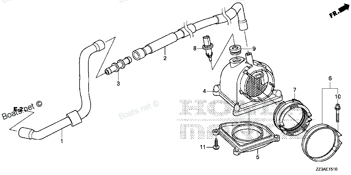
17202-ZZ3-000 PLATE, AIR GUIDE Honda
BF60AK1 LRTA, BF60AK1 XRTA, BFP60AK1 LRTA, BFP60AK1 LRTB, BFP60AK1 XRTA
PLATE

Price: query
You can buy parts:
As an associate, we earn commssions on qualifying purchases through the links below

$5.18
24-09-2017
.19[0.00] pounds
Honda: Honda
Honda 17202-ZZ3-000 Plate, Air Guide; 17202ZZ3000 Made by Honda
New
New
Number on catalog scheme: 5
Compatible models:
Honda entire parts catalog list:
Information:
2. Disconnect tube assembly (1) from the muffler.3. Remove two clamps (2) that hold the muffler in position.4. Fasten a hoist to muffler (3). Remove the muffler from the engine. Weight of the muffler is 95 lb. (43 kg). 5. Remove two bolts (5) and bracket (6).6. Remove bolts (9) that hold the turbocharger oil supply tube in position. Remove the tube (11). Remove the oil return line for the turbocharger. The location of the line is under the turbocharger. Loosen the two clamps that hold hose (12) in position. Slide the hose off of the housing assembly of the turbocharger.7. Remove pipe (4) from the turbocharger.8. Remove four bolts (7) that hold elbow (8) to the cylinder head.9. Remove four bolts (10) and nuts that hold the turbocharger to the exhaust manifold. 10. Remove turbocharger (13) from the engine. Remove elbow (8) from the turbocharger.Install Turbocharger
1. Install elbow (2) on the turbocharger as shown.2. Put 5P3931 Anti-Seize Compound on the threads of the four bolts that hold the turbocharger to the exhaust manifold.3. Put turbocharger (1) in position on the exhaust manifold. Install the four bolts and nuts that hold it. Tighten the nuts to a torque of 45 5 lb. ft. (60 7 N m). 4. Install four bolts (6) that hold pipe (2) to the cylinder head.5. Install the oil return tube under the turbocharger.6. Install oil supply tube (7). Install pipe (3) on the turbocharger.7. Slide hose (9) in position on the turbocharger and tighten two clamps (8) that hold it.8. Put bracket (5) in position and install bolts (4) that hold it. 9. Fasten a hoist to muffler (10) and put it in position on the brackets that hold it.10. Install the two clamps over the muffler.11. Connect the tube assembly from the air cleaner assembly to the muffler.12. Install the hood.Disassemble Turbocharger
start by:a) remove turbocharger 1. Put the turbocharger in position on tool (A).2. Put a mark on the compressor cover and housings for installation purposes.3. Remove "V" clamp (2) and remove compressor cover (1). 4. Remove "V" clamp (3) and remove shaft housing from turbine housing (4). 5. Put shaft housing in tool (B). Remove nut and compressor wheel (5) from the shaft.
When the nut is loosened, do not put a side force on the shaft.
6. Remove shaft housing from tool (B) and remove turbine wheel (7) and shaft from housing.7. Remove seal ring (6) from the turbine wheel. 8. Remove snap ring and insert (8) from the housing. 9. Push the sleeve (9) out of the insert. Remove the two seal rings from the sleeve. 10. Remove deflector (10), ring (15), sleeve (11), bearing (12), ring (16), snap ring (13), bearing (17) and snap ring (14) from the housing. Remove snap rings (13) and (14) with tool (C). Check the oil hole in bearing (12). If the oil hole is not open this will cause a bearing failure. 11. Turn the housing around and remove snap ring (18) and shroud (22).12. Remove snap ring (19), sleeve (20), bearing (21) and snap ring (23). Remove the two snap rings with tool (C).13. Install all parts and install new parts as needed.Assemble Turbocharger
1. Make sure all oil passages are open and clean. Put clean engine oil on all parts before assembly. 2. Install snap ring (4), bearing (3), sleeve (2) and snap ring (1). Install the two snap rings with tool (A). Install the snap rings with the round side toward the bearing. 3. Install shroud (5) on the housing. Turn the shroud to make sure it is down on the housing even. The high part (web) (6) on shroud, will keep the shroud from turning on the housing after assembly.4. Install snap ring that holds the shroud in place.5. Install the bearing and two snap rings in the compressor end of the housing. Install the snap rings with tool (A). Install the snap rings with the round side toward the bearing. 6. Install seal ring (7) on the shaft. Install turbine wheel (8) and shaft in the housing.7. Put housing in position on tool (B). 8. Install ring (13), bearing (11), sleeve (12), ring (10) and deflector (9) in the housing.
The oil hole in bearing (11) must be open and clean.
9. Install the seal rings on sleeve (15). Install sleeve in insert (14). 10. Install insert in the housing and install snap ring (17).11. Install compressor wheel (16) on shaft. 12. Put clean engine oil on the threads of the shaft. Install the nut (18) and tighten to a torque of 15 1 lb.ft. (20 1 N m).
When the nut is tightened, do not put a side force on the shaft.
13. Install shaft housing into the turbine housing. Install "V" clamp (21) and tighten clamp to a torque of 120 lb.in. (13.6 N m).14. Install compressor cover (19) and "V" clamp (20). Tighten "V" clamp to a torque of 120 lb.in. (13.6 N m).end by:a) install turbocharger
Parts plate Honda:
24818-ZW5-U01
24818-ZW5-U01 PLATE, CABLE CLAMP (Honda Code 6799639).
BF115A1 LA, BF115A1 LCA, BF115A1 XA, BF115A1 XCA, BF115A2 LA, BF115A2 LCA, BF115A2 XA, BF115A2 XCA, BF115A3 LA, BF115A3 LCA, BF115A3 XA, BF115A3 XCA, BF115A4 LA, BF115A4 LCA, BF115A4 XA, BF115A4 XCA, BF115A5 LA, BF115A5 LCA, BF115A5 XA, BF115A5 XCA,
24817-ZW5-U01
24817-ZW5-U01 PLATE, HANDLE
BF115A3 LA, BF115A3 LCA, BF115A3 XA, BF115A3 XCA, BF115A4 LA, BF115A4 LCA, BF115A4 XA, BF115A4 XCA, BF115A5 LA, BF115A5 LCA, BF115A5 XA, BF115A5 XCA, BF115A6 LA, BF115A6 LCA, BF115A6 XA, BF115A6 XCA, BF115AK0 LA, BF115AK0 XA, BF115DK1 LA, BF115DK1 XA
14221-ZZ3-003
14221-ZZ3-003 PLATE, TDC PULSER
BF60AK1 LRTA, BF60AK1 XRTA, BFP60AK1 LRTA, BFP60AK1 LRTB, BFP60AK1 XRTA
19286-ZZ3-000
50218-ZZ3-000
50218-ZZ3-000 PLATE, FRICTION
BF60AK1 LRTA, BF60AK1 XRTA, BFP60AK1 LRTA, BFP60AK1 LRTB, BFP60AK1 XRTA
35645-ZZ3-A41
50221-ZZ3-000
50221-ZZ3-000 PLATE, STEERING ANGLE SENSOR
BF60AK1 LRTA, BF60AK1 XRTA, BFP60AK1 LRTA, BFP60AK1 LRTB, BFP60AK1 XRTA
17860-ZZ3-000
17860-ZZ3-000 PLATE, THROTTLE
BF60AK1 LRTA, BF60AK1 XRTA, BFP60AK1 LRTA, BFP60AK1 LRTB, BFP60AK1 XRTA