90855-921-300 PLUG, SEALING (10MM) (Honda Code 0285395). Honda
BF8A3 LA, BF8A3 SA, BF8A4 LA, BF8A4 SA, BF8A5 LA, BF8A5 SA, BF8A6 LA, BF8A6 SA, BF8AK0 LA, BF8AK0 SA, BF8AM LA, BF8AM SA, BF8AM XA, BF8AW LA, BF8AW SA, BF8AW XA, BF8AX LA, BF8AX SA, BF8AX XA, BF8AY LA, BF8AY SA, BF8AY XA
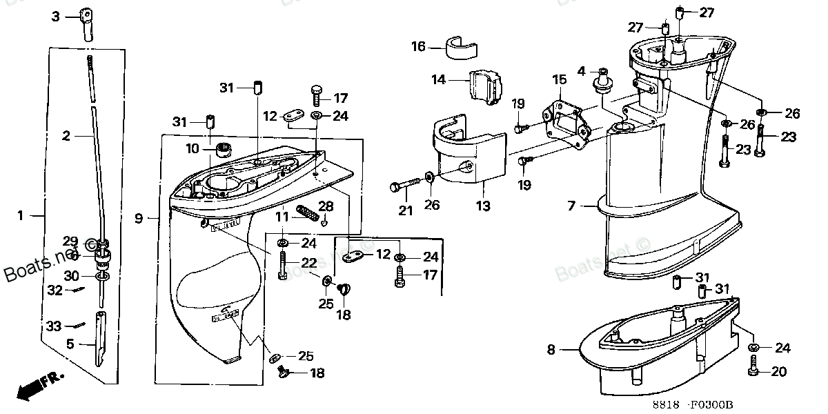
PLUG
 (Honda Code 0285395). Honda parts")
Price: query
Rating:
You can buy parts:
As an associate, we earn commssions on qualifying purchases through the links below

Number on catalog scheme: 28
Compatible models:
Honda entire parts catalog list:
- EXTENSION CASE » 90855-921-300
- EXTENSION CASE » 90855-921-300
- EXTENSION CASE » 90855-921-300
- EXTENSION CASE » 90855-921-300
- EXTENSION CASE » 90855-921-300
- EXTENSION CASE » 90855-921-300
- EXTENSION CASE » 90855-921-300
- EXTENSION CASE » 90855-921-300
- EXTENSION CASE » 90855-921-300
- EXTENSION CASE » 90855-921-300
- EXTENSION CASE » 90855-921-300
- EXTENSION CASE » 90855-921-300
- EXTENSION CASE » 90855-921-300
- EXTENSION CASE » 90855-921-300
- EXTENSION CASE » 90855-921-300
- EXTENSION CASE » 90855-921-300
- EXTENSION CASE » 90855-921-300
- EXTENSION CASE » 90855-921-300
- EXTENSION CASE » 90855-921-300
- EXTENSION CASE » 90855-921-300
- EXTENSION CASE » 90855-921-300
- EXTENSION CASE » 90855-921-300
Information:
Table 1
Required Tools
Tool Part Number Part Description Qty
A 473-2944 Capping Kit 1
B - De-ionized Water 1
Ensure that all adjustments and repairs that are carried out to the Diesel Exhaust Fluid (DEF) system are performed by authorized personnel that have the correct training.Before beginning ANY work on the DEF system, refer to Operation and Maintenance Manual, "General Hazard" for safety information.
Care must be taken to ensure that Diesel Exhaust Fluid (DEF) for the system are contained during performance of inspection, maintenance, testing, adjusting, and repair of the product. Be prepared to collect the fluid with suitable containers before opening any compartment or disassembling any component containing fluids.Dispose of all fluids according to local regulations and mandates.
Ensure that the purge process for the DEF system is completed before turning the battery disconnect switch to the OFF position. Refer to the Operation and Maintenance Manual, "Battery Disconnect Switch" for further information.
Turn turning the battery disconnect switch to the OFF position.
Illustration 1 g06491862
Illustration 2 g06149190
Ensure that the area around Diesel Exhaust Fluid (DEF) injector (4) is clean and free dirt and debris. If necessary, clean the area around the DEF injector. Clean the area around the DEF injector with Tooling (B) and a suitable tool.
Drain the coolant from the cooling system into a suitable container for storage or disposal. Refer to Operation and Maintenance Manual, "Coolant - Change" for the correct procedure.
Remove the Diesel Exhaust Fluid (DEF) line from connection (3) on DEF injector (4). Refer to Disassembly and Assembly, "Diesel Exhaust Fluid Lines - Remove and Install" for the correct procedure. Use Tooling (A) to cap connection (3) on DEF injector (4) and plug the DEF line.
Remove the coolant lines from connection (1) and connection (2) on DEF injector (4). Use Tooling (A) to cap the connections on the DEF injector and plug the coolant lines.
Ensure that no Diesel Exhaust Fluid (DEF) enters the harness assembly or the harness connection.
Disconnect the harness assembly from connection (8) on DEF injector (4). Use Tooling (A) to cap the harness assembly and the connection on the DEF injector.
Remove bolts (7) and washers (6) (not shown). Remove DEF injector (4) from mixer module (5).
Remove gasket seal (9) from DEF injector (4).Note: To remove the mixer module the DEF injector removal is not required. Removal of the DEF lines and the electrical connection is required. Refer to Disassembly and Assembly, "Diesel Exhaust Fluid Lines - Remove and Install" for the correct procedure.
Illustration 3 g06491863
Illustration 4 g06491865
If necessary, follow Step 10a through Step 10g to remove mixer module (5).
Sufficiently loosen V-band clamp (10) and position V-band clamp (10) away from mixer module (5), to allow removal of mixer module (5).
Sufficiently loosen V-band clamp (12) and position V-band clamp (12) away from mixer module (5), to allow removal of mixer module (5) from Selective Catalyst Reduction (SCR) (11)
If the V-band clamp (10) and V-band clamp (12) remain tight on the flanges, apply releasing fluid on the V-band clamps to assist removal. Lightly tap the bolts on the V-band clamps with a soft faced hammer to assist removal. Do not use a prybar to remove V-band clamps.
Remove mixer module (5) from SCR (11) and combined DOC and DPF (13).
Remove seal (14) and sealing ring (15) from mixer tube (5).
Remove seal (17) and sealing ring (16) from mixer tube (5).
Remove the V-band clamps, seals, and sealing rings and discard.Installation Procedure
Table 2
Required Tools
Tool Part Number Part Description Qty
B - De-ionized Water 1
Ensure that the DEF injector and the mixer module are free from wear and damage. Replace any component that is worn or damaged.
Illustration 5 g06491865