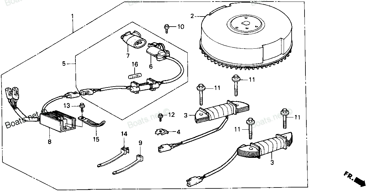
31650-ZV1-A02 RECEPTACLE ASSY., CHARGE (Honda Code 7531627). Honda
BF5A1 LA, BF5A1 SA, BF5A2 LA, BF5A2 SA, BF5A3 LA, BF5A3 SA, BF5A4 LA, BF5A4 SA, BF5A5 LA, BF5A5 SA, BF5A6 LA, BF5A6 SA, BF5AK0 LA, BF5AK0 SA, BF5AK2 LA, BF5AK2 SA, BF5AK3 LA, BF5AK3 SA
RECEPTACLE
. Honda parts")
Price: query
Rating:
Number on catalog scheme: 5
Compatible models:
Honda entire parts catalog list:
- CHARGE RECEPTACLE KIT » 31650-ZV1-A02
- CHARGE RECEPTACLE KIT » 31650-ZV1-A02
- CHARGE RECEPTACLE KIT » 31650-ZV1-A02
- CHARGE RECEPTACLE KIT » 31650-ZV1-A02
- CHARGE RECEPTACLE KIT » 31650-ZV1-A02
- CHARGE RECEPTACLE KIT » 31650-ZV1-A02
- CHARGE RECEPTACLE KIT » 31650-ZV1-A02
- CHARGE RECEPTACLE KIT » 31650-ZV1-A02
- CHARGE RECEPTACLE KIT » 31650-ZV1-A02
- CHARGE RECEPTACLE KIT » 31650-ZV1-A02
- CHARGE RECEPTACLE KIT » 31650-ZV1-A02
- CHARGE RECEPTACLE KIT » 31650-ZV1-A02
- CHARGE RECEPTACLE KIT » 31650-ZV1-A02
- CHARGE RECEPTACLE KIT » 31650-ZV1-A02
- CHARGE RECEPTACLE KIT » 31650-ZV1-A02
- CHARGE RECEPTACLE KIT » 31650-ZV1-A02
- CHARGE RECEPTACLE KIT » 31650-ZV1-A02
- CHARGE RECEPTACLE KIT » 31650-ZV1-A02
Information:
Table 1
J1939 Code and Description CDL Code and Description Comments
91-3
Accelerator Pedal Position #1 : Voltage Above Normal 91-3
Throttle Position Sensor : Voltage Above Normal The Electronic Control Module (ECM) detects signal voltage that is not in the acceptable range.
The code is logged. The ECM flags the throttle position as invalid data and a default value is used. The engine speed is limited to high idle.
91-4
Accelerator Pedal Position #1 : Voltage Below Normal 91-4
Throttle Position Sensor : Voltage Below Normal The ECM detects signal voltage that is not in the acceptable range.
The code is logged. The ECM flags the throttle position as invalid data and a default value is used. The engine speed is limited to high idle.
91-8
Accelerator Pedal Position #1 : Abnormal Frequency, Pulse Width, or Period 91-8
Throttle Position Sensor : Abnormal Frequency, Pulse Width, or Period The ECM detects an incorrect frequency on the throttle signal or an incorrect duty cycle on the throttle signal.
The code is logged. The ECM flags the throttle position as invalid data and a default value is used. The engine speed is limited to high idle. Note: Performing steps within this procedure requires the use of a multimeter capable of measuring a PWM duty cycle and frequency.
Table 2
Required Tools
Part Number Part Name Qty
7X-1710 Multimeter Probe 1
146-4080 Digital Multimeter Gp 1
326-4904 Adapter Cable As 1
Illustration 1 g03889309
Table 3
Troubleshooting Test Steps Values Results
1. Check for Codes
A. Connect Cat® Electronic Technician (ET) to the service tool connector.
B. Determine if a code is active or logged.
Codes
Result: A -3 code is active or logged.
Proceed to Test Step 2.
Result: A -4 code is active or logged.
Proceed to Test Step 3.
Result: A -8 code is active or logged.
Proceed to Test Step 5.
2. Create a Short at the Sensor Connector
A. Turn the keyswitch to the OFF position.
B. Disconnect the sensor with the active -3 code.
C. Install the jumper wire between the following terminals at the sensor connector:
- Pin 2 (sensor return) and Pin 3 (sensor signal)
D. Connect Cat ET.
E. Use Cat ET to monitor the following:
- -4 code
F. Turn the keyswitch to the OFF position.
Create a Short
Result: A -4 code became active.
Repair: The wiring harness is OK. Replace the sensor.
Verify that the repair eliminated the problem.
Result: A -4 code did not become active.
Proceed to Test Step 4.
3. Create an Open at the Sensor Connector
A. Turn the keyswitch to the OFF position.
B. Disconnect the sensor with the active -4 code.
C. Connect Cat ET.
D. Use Cat ET to monitor the following:
- -3 code
E. Turn the keyswitch to the OFF position.
Create an Open
Result: A -3 code became active.
Repair: The wiring harness is OK. Replace the sensor.
Verify that the repair eliminated the problem.
Result: A -3 code did not become active.
Proceed to Test Step 4.
4. Check the 24 VDC Supply Voltage at the Sensor Connector
A. Turn the keyswitch to the ON position.
B. Measure the voltage at the following pin locations of the affected sensor connector:
- Pin 1 and Pin 2
C. Reconnect the sensor.
Supply Voltage
Result: The supply voltage is approximately 24.0 0.2 VDC
Proceed to Test Step 8.
Result: The supply voltage is not approximately 24.0 0.2 VDC.
Repair: There is a short in the wiring harness to the battery. Repair or replace the wiring harness.
If the problem is not resolved, proceed to Test Step 5.
5. Check the PWM Circuit for an Open
A. Turn the keyswitch to the OFF position.
B. Disconnect the sensor with the active -8 code.
C. Disconnect the J2 connector at the ECM.
D. Measure the resistance between the following locations for the sensor:
- Pin 3 (sensor connector) and the appropriate PWM signal wire on the ECM connector
Open Circuit
Result: Less than 10 ohms of resistance between the sensor connector and the ECM connector.
Proceed to Test Step 6.
Result: More than 10 ohms of resistance between the sensor connector and the ECM connector.
There is an open circuit in the wiring harness. Repair or replace the wiring harness.
If the problem is not resolved, proceed to Test Step 6.
6. Check the PWM Circuit for a Short Circuit
A. Turn the keyswitch to the OFF position
B. Disconnect the sensor with the active -8 code.
C. Disconnect the J2 connector at the ECM.
D. Measure the resistance between the following locations for the sensor:
- Pin 3 (sensor connector) and Engine ground
Short Circuit
Result: There were more than 100 K ohms of resistance between pin 3 and engine ground.
Proceed to Test Step 7.
Result: There were less than 100 K ohms of resistance between pin 3 and engine ground.
There is a short circuit in the wiring harness. Repair or replace the wiring harness.
If the problem is not resolved, proceed to Test Step 7.
7. Check the PWM Circuit for a Pin to Pin Short Circuit
A. Turn the keyswitch to the OFF position.
B. Disconnect the sensor with the active -8 code.
C. Disconnect the J2 connector at the ECM.
D. Measure the resistance between the following locations for the sensor:
- Pin 3 (sensor connector) and all ECM connector pins
Short Circuit
Result: There were more than 100 K ohms of resistance between the signal pin at the ECM and all other pins in the ECM connector.
Proceed to Test Step 8.
Result: There were less than 100 K ohms of resistance between the signal pin at the ECM and all other pins in the ECM connector.
There is a short circuit in the wiring harness. Repair or replace the wiring harness
If the problem is not resolved, proceed to Test Step 8.
8. Perform the Wiggle Test
Carefully following this procedure is the best way to identify the root cause of an intermittent problem.
A. Turn the keyswitch to the ON position.
B. Connect Cat ET.
C. Use CAT ET to perform the following test:
- "Wiggle Test"
D. Slowly wiggle the wiring and the connectors between the P2 connector and the sensor. Pay particular attention to the wiring near each connector. Be sure to wiggle all the wiring. As you wiggle the wiring look for the following problems:
- Loose connectors or damaged connectors
- Moisture on the connectors or the wiring
- Damaged that is caused by excessive heat
- Damage that is caused by chafing
- Improper routing of wiring
- Damaged insulation
Test
Result: The wiring failed the
Parts receptacle Honda:
06310-ZV1-A00
06310-ZV1-A00 RECEPTACLE KIT, CHARGE (Honda Code 3749025).
BF5A1 LA, BF5A1 SA, BF5A2 LA, BF5A2 SA, BF5A3 LA, BF5A3 SA, BF5AK2 LA, BF5AK2 SA, BF5AM LA, BF5AM SA, BF5AW LA, BF5AW SA, BF5AX LA, BF5AX SA, BF5AY LA, BF5AY SA
31650-ZV1-A01
31650-ZV1-A01 RECEPTACLE ASSY., CHARGE (Honda Code 3749207).
BF5A1 LA, BF5A1 SA, BF5A2 LA, BF5A2 SA, BF5A3 LA, BF5A3 SA, BF5AK2 LA, BF5AK2 SA, BF5AM LA, BF5AM SA, BF5AW LA, BF5AW SA, BF5AX LA, BF5AX SA, BF5AY LA, BF5AY SA
31651-ZV1-A01

31651-ZV1-A01 RECEPTACLE (Honda Code 5711650).
BF5A1 LA, BF5A1 SA, BF5A2 LA, BF5A2 SA, BF5A3 LA, BF5A3 SA, BF5A4 LA, BF5A4 SA, BF5A5 LA, BF5A5 SA, BF5A6 LA, BF5A6 SA, BF5AK0 LA, BF5AK0 SA, BF5AK2 LA, BF5AK2 SA, BF5AK3 LA, BF5AK3 SA, BF5AM LA, BF5AM SA, BF5AW LA, BF5AW SA, BF5AX LA, BF5AX SA, BF5A
06310-ZV1-F01ZA
06310-ZV1-F01ZA RECEPTACLE KIT, CHARGE *TBLACK* (BLACK)
BF5A2 LA, BF5A2 SA, BF5A3 LA, BF5A3 SA, BF5A4 LA, BF5A4 SA, BF5A5 LA, BF5A5 SA, BF5A6 LA, BF5A6 SA, BF5AK0 LA, BF5AK0 SA, BF5AK2 LA, BF5AK2 SA, BF5AK3 LA, BF5AK3 SA