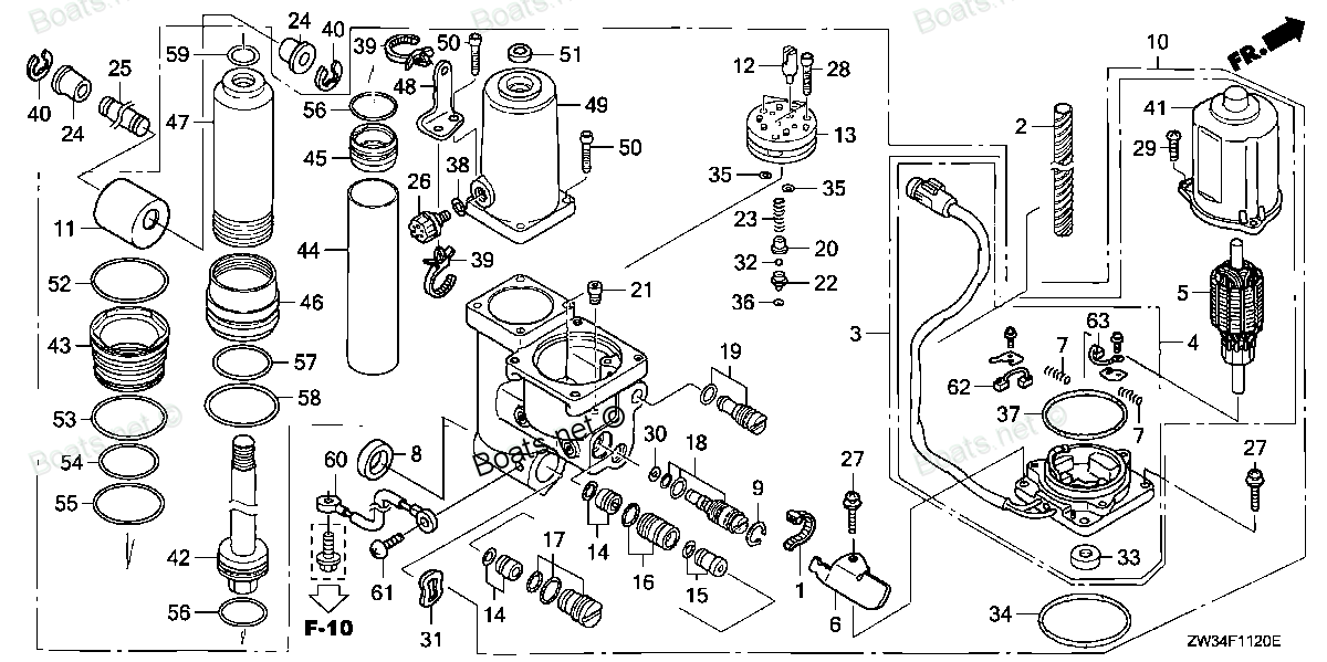
56110-ZW4-H11 ROD, PISTON (Honda Code 7756976). Honda
BF40A4 LHTA, BF40A4 LRTA, BF40A5 LHTA, BF40A5 LRTA, BF40A6 LHTA, BF40A6 LRTA, BF40AK0 LRTA, BF40DK2 LRTA, BF50A4 LHTA, BF50A4 LRTA, BF50A4 SRJA, BF50A4 XRTA, BF50A5 LHTA, BF50A5 LRTA, BF50A5 SRJA, BF50A5 XRTA, BF50A6 LHTA, BF50A6 LRTA, BF50A6 SRJA, B
ROD
. Honda parts")
Price: query
Rating:
Number on catalog scheme: 42
Compatible models:
BF40A4 LHTA
BF40A4 LRTA
BF40A5 LHTA
BF40A5 LRTA
BF40A6 LHTA
BF40A6 LRTA
BF40AK0 LRTA
BF40DK2 LRTA
BF50A4 LHTA
BF50A4 LRTA
BF50A4 SRJA
BF50A4 XRTA
BF50A5 LHTA
BF50A5 LRTA
BF50A5 SRJA
BF50A5 XRTA
BF50A6 LHTA
BF50A6 LRTA
BF50A6 SRJA
BF50A6 XRTA
BF50AK0 LRTA
BF50AK0 SRJA
BF50AK0 XRTA
BF50DK2 LRTA
BF50DK2 XRTA
BF60AK1 LRTA
BF60AK1 XRTA
BFP60AK1 LRTA
BFP60AK1 LRTB
BFP60AK1 XRTA
Honda
Honda entire parts catalog list:
- POWER TRIM-TILT » 56110-ZW4-H11
- POWER TRIM-TILT » 56110-ZW4-H11
- POWER TRIM-TILT » 56110-ZW4-H11
- POWER TRIM-TILT » 56110-ZW4-H11
- POWER TRIM-TILT » 56110-ZW4-H11
- POWER TRIM-TILT » 56110-ZW4-H11
- POWER TRIM-TILT » 56110-ZW4-H11
- POWER TRIM-TILT » 56110-ZW4-H11
- POWER TRIM-TILT » 56110-ZW4-H11
- POWER TRIM-TILT » 56110-ZW4-H11
- POWER TRIM-TILT » 56110-ZW4-H11
- POWER TRIM-TILT » 56110-ZW4-H11
- POWER TRIM-TILT » 56110-ZW4-H11
- POWER TRIM-TILT » 56110-ZW4-H11
- POWER TRIM-TILT » 56110-ZW4-H11
- POWER TRIM-TILT » 56110-ZW4-H11
- POWER TRIM-TILT » 56110-ZW4-H11
- POWER TRIM-TILT » 56110-ZW4-H11
- POWER TRIM-TILT » 56110-ZW4-H11
- POWER TRIM-TILT » 56110-ZW4-H11
- POWER TRIM-TILT » 56110-ZW4-H11
- POWER TRIM-TILT » 56110-ZW4-H11
- POWER TRIM-TILT » 56110-ZW4-H11
- POWER TRIM-TILT » 56110-ZW4-H11
- POWER TRIM-TILT » 56110-ZW4-H11
- POWER TRIM-TILT » 56110-ZW4-H11
- POWER TRIM-TILT » 56110-ZW4-H11
- POWER TRIM-TILT » 56110-ZW4-H11
- POWER TRIM-TILT » 56110-ZW4-H11
- POWER TRIM-TILT » 56110-ZW4-H11
Information:
1. Turn the crankshaft until the timing mark on the crankshaft gear (2) is in alignment with the timing mark on the camshaft gear (1). Check the bearing caps for a number as to their location. If a number can not be seen, put a number on the left side of cap and cylinder block.
TYPICAL EXAMPLE2. Fasten a hoist to the crankshaft.3. Remove the caps for the main bearings.4. Remove the crankshaft. Weight is 145 lb. (66 kg).5. Remove the crankshaft main bearings from the cylinder block and caps. 6. Remove the crankshaft gear (3) with tooling (A).Install Crankshaft
1. Heat the crankshaft drive gear and install it on the crankshaft. Maximum temperature to be used on crankshaft gear is 600°F (315°C).2. Clean the surfaces on the cylinder block for the bearings. Install the upper halves of the main bearings in the block. Put clean oil on the bearings. 3. Fasten a hoist to the crankshaft and put it into position in the cylinder block. The timing marks (1) on the crankshaft gear and camshaft gear must be in alignment as shown. 4. Clean the main bearing caps. Install the lower halves of the main bearings in caps. 5. Check the main bearing clearance with wire (A). Install the wire between the crankshaft and bearing. Install the caps in their correct places. Be sure the number on the cap is toward the number on the pan surface of the left side of the cylinder block.6. Put clean oil on the threads of the bolts and on the faces of the washers that hold the main bearing caps. Install the bolts and washers. Tighten both bolts to 30 3 lb.ft. (4.1 0.4 mkg). Put a mark on the bolt heads and bearing caps. Tighten the bolts 90° from the mark as shown. Remove bearing caps and measure the thickness of the wire (A). Main bearing clearance (wire thickness) with new bearings must be .0030 to .0059 in. (0.076 to 0.150 mm). Maximum permissible clearance with used bearings is .010 in. (0.25 mm).7. Put clean oil on the lower halves of main bearings. Install the caps in their correct places. Install the bolts and washers. Tighten bolts to 30 3 lb.ft. (4.1 0.4 mkg). Put a mark on the bolt heads and caps. Tighten each bolt 90° from the mark. 8. Check the crankshaft end clearance with tool group (B). End clearance is controlled by the thrust bearing (2) on the rear main. End clearance with new bearings must be .0025 to .0145 in. (0.064 to 0.368 mm). Maximum permissible end clearance with used bearings is .025 in. (0.64 mm). Install thrust bearing with side marked "BLOCK SIDE" toward the cylinder block.9. If the accessory drive gear, idler gear or camshaft gear has been removed or a replacement has been made, it is necessary to put the fuel injection pump into correct time after the engine is assembled. See REMOVE AND INSTALL FUEL INJECTION PUMP HOUSING AND GOVERNOR.end by: a) install pistonsb) install timing gear coverc) install flywheel housingd) install engine
Parts rod Honda:
17853-ZV5-000

17853-ZV5-000 ROD, STEERING (Honda Code 3702347).
BF15D3 LRA, BF15D3 LRTA, BF15D3 SHA, BF15D3 SHSA, BF15D3 SRTA, BF15D4 LRA, BF15D4 LRTA, BF15D4 SRTA, BF15D5 LGA, BF15D5 LHA, BF15D5 LHGA, BF15D5 LHSA, BF15D5 LHTA, BF15D5 LRA, BF15D5 LRTA, BF15D5 SRTA, BF15D5 XHA, BF15D5 XHGA, BF15D6 LHA, BF15D6 LHSA
24320-ZW1-B00
24320-ZW1-B00 ROD A, SHIFT (L) (Honda Code 5891718).
BF115A1 LA, BF115A1 LCA, BF115A1 XA, BF115A1 XCA, BF115A2 LA, BF115A2 LCA, BF115A2 XA, BF115A2 XCA, BF115A3 LA, BF115A3 LCA, BF115A3 XA, BF115A3 XCA, BF115A4 LA, BF115A4 LCA, BF115A4 XA, BF115A4 XCA, BF115A5 LA, BF115A5 LCA, BF115A5 XA, BF115A5 XCA,
53122-ZW4-H01
53122-ZW4-H01 ROD, GROMMET
BF25DK0 LRGA, BF25DK0 LRTA, BF25DK0 SHGA, BF25DK2 LRGA, BF25DK2 LRTA, BF25DK2 SHGA, BF25DK3 LRGA, BF25DK3 LRTA, BF25DK3 SHGA, BF30DK0 LRGA, BF30DK0 LRTA, BF30DK0 SRTA, BF30DK2 LRGA, BF30DK2 LRTA, BF30DK2 SRTA, BF30DK3 LRGA, BF30DK3 LRTA, BF30DK3 SRTA
13210-ZZ5-000
50340-ZZ5-000
50340-ZZ5-000 ROD, ADJUSTING
BF40DK2 LHA, BF40DK2 LRTA, BF50DK2 LRTA, BF50DK2 XRTA, BF60AK1 LRTA, BF60AK1 XRTA, BFP60AK1 LRTA, BFP60AK1 LRTB, BFP60AK1 XRTA
17840-ZZ5-000
53238-ZZ3-610
24310-ZZ3-000