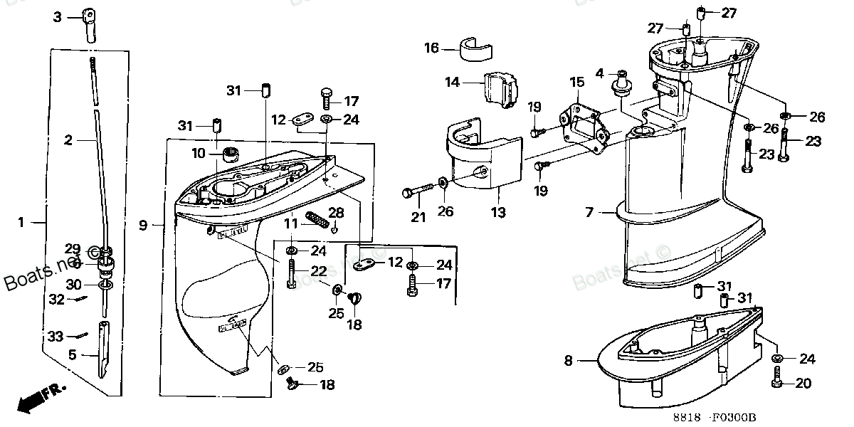
50153-881-000 RUBBER B, SETTING (LOWER) (Honda Code 0498980). Honda
BF8A3 LA, BF8A3 SA, BF8A4 LA, BF8A4 SA, BF8A5 LA, BF8A5 SA, BF8A6 LA, BF8A6 SA, BF8AK0 LA, BF8AK0 SA, BF8AM LA, BF8AM SA, BF8AW LA, BF8AW SA, BF8AX LA, BF8AX SA, BF8AY LA, BF8AY SA
RUBBER
 (Honda Code 0498980). Honda parts")
Price: query
Rating:
You can buy parts:
As an associate, we earn commssions on qualifying purchases through the links below

$19.50
31-03-2024
0.25[0.11] Pounds
US: PowerToolReplacement
Honda 50153-881-000 Rubber B Mounting
Honda Honda 50153-881-000 Rubber B Mounting
Honda Honda 50153-881-000 Rubber B Mounting
Number on catalog scheme: 16
Compatible models:
Honda entire parts catalog list:
- EXTENSION CASE » 50153-881-000
- EXTENSION CASE » 50153-881-000
- EXTENSION CASE » 50153-881-000
- EXTENSION CASE » 50153-881-000
- EXTENSION CASE » 50153-881-000
- EXTENSION CASE » 50153-881-000
- EXTENSION CASE » 50153-881-000
- EXTENSION CASE » 50153-881-000
- EXTENSION CASE » 50153-881-000
- EXTENSION CASE » 50153-881-000
- EXTENSION CASE » 50153-881-000
- EXTENSION CASE » 50153-881-000
- EXTENSION CASE » 50153-881-000
- EXTENSION CASE » 50153-881-000
- EXTENSION CASE » 50153-881-000
- EXTENSION CASE » 50153-881-000
- EXTENSION CASE » 50153-881-000
- EXTENSION CASE » 50153-881-000
Information:
Illustration 1 g06472200
Fuel system schematic
(1) Fuel gallery
(2) Mechanical electronic unit injectors
(3) Fuel pressure regulators
(4) Fuel return line
(5) Fuel cooler (if equipped)
(6) Tank breather filter
(7) Fuel tank
(8) Fuel supply line
(9) Fuel/water separator
(10) Electric fuel priming pump
(11) Fuel transfer pump
(12) Check valve
(13) Electronic control module (ECM)
(14) Fuel temperature sensor
(15) Pressure relief valve
(16) Secondary fuel filter
(17) Differential pressure switch (If equipped)
(18) Tertiary fuel filter
(19) Fuel pressure sensor (If equipped)
(20) Secondary fuel filter base
(21) Fuel tank return check valve (Fuel return manifold)The fuel supply circuit is a conventional design for unit injector diesel engines. The system consists of the following major components that are used to deliver low-pressure fuel to the unit injectors:Fuel tank - The fuel tank is used to store the fuel.Fuel priming pump - The fuel priming pump is used to evacuate the air from the fuel system. As the air is removed, the system fills with fuel.Fuel filters - The fuel/water separator is a 10 micron filter with a water separator. This filter is used to remove abrasive material and contamination from the fuel system that may be large enough to damage the fuel transfer pump. The secondary fuel filter, which is located on the secondary fuel filter base, is used to remove abrasive material and contamination. As small as 2 microns that could damage the injectors. The tertiary fuel filter is located on the secondary fuel filter base. The tertiary fuel filter is used to remove abrasive materials and contamination as small as 4 microns. A differential pressure switch is utilized on the secondary fuel filter base in order to indicate the life of the fuel filter.Supply lines and return lines - Supply lines and return lines are used to deliver the fuel to the different components.The purpose of the low-pressure fuel supply circuit is to supply fuel that has been filtered to the fuel injectors at a rate and a pressure that is constant. The fuel system is also utilized to cool components such as the fuel injectors.Once the injectors receive the low-pressure fuel, the fuel is pressurized again before the fuel is injected into the cylinder. The unit injector uses mechanical energy that is provided by the camshaft to achieve pressures that can be in excess of 200000 kPa (30000 psi).Control of the fuel delivery is managed by the Electronic Control Module (ECM) of the engine. Data from several of the engine systems is collected by the ECM and processed in order to manage these aspects of fuel injection control:
Injection timing
Fuel injection timing advance
Injection duration
Engine cold mode statusThe mechanical electronic fuel system relies on a large amount of data from the other engine systems. The data that is collected by the ECM will be used in order to provide optimum performance of the engine.Low Pressure Fuel Supply Circuit
The flow of fuel through the system begins at fuel tank (7). Fuel that is drawn from the tank by the fuel transfer pump (11) is filtered through a fuel/water separator. The separator is a 10 micron filter with a water separator. Fuel flows from the filter to the fuel transfer pump. The fuel transfer pump incorporates a check valve (12). The fuel transfer pump will allow fuel to flow around the gears of the pump during priming of the fuel system. The fuel transfer pump also incorporates a pressure relief valve (15). The pressure relief valve is used in order to protect the fuel system from extreme pressure.The fuel transfer pump is engineered in order to produce an excess fuel flow throughout the fuel system. The excess fuel flow is used by the system to cool the fuel system components. The excess fuel flow also purges any air from the fuel system during operation. Air that can become trapped in the fuel system can cause cavitation that may damage the components of the unit injector.The fuel priming pump (10) is located on the fuel/water separators base. The fuel filter base and fuel/water separator (9) also incorporate a siphon break. The siphon break prevents fuel from draining from the fuel system when the engine is not in operation. The priming pump is an electric pump that directs the flow of fuel during the priming pump operation. The fuel flows through a secondary fuel filter base which contains the following filters: secondary and tertiary. The secondary filter (16) is a 2 micron fuel filter that is used in order to remove small abrasive particles that will cause premature wear to fuel system components. The tertiary filter (17) is a 4 micron filter that is used to remove small abrasive particles. The filtered fuel then flows out of the fuel filter and returns to the passages in the fuel filter base. Prior to exiting the fuel filter base, the fuel pressure and the fuel temperature is sampled by the fuel pressure sensor (19) and by the fuel temperature sensor (14). The signals that are generated by the sensors are used by the engine control in order to monitor the condition of the engine components. This information is also used to adjust the fuel delivery of the engine in order to optimize efficiency. A differential pressure switch (17) is also used in order to indicate life of the fuel filter.The fuel is transferred by fuel supply lines (8) to the fuel gallery (1) in the cylinder head. Only a portion of the fuel that is supplied to the fuel injectors is used for engine operation. This unused fuel is discharged into the return passages of the fuel gallery. The fuel is returned to the fuel tank by the fuel return lines (4). The fuel flows through the fuel return manifold that contains fuel tank return check valve (21). The normal operating pressure of the check valve is 41 kPa (6 psi) and the cracking pressure is 14 4 kPa (2 0.6 psi). A continuous flow of fuel is experienced within the low-pressure fuel system.During engine operation, fuel injectors (2) receive fuel from the low-pressure fuel system. The injector pressurizes the
Parts rubber Honda:
19302-921-003

19302-921-003 RUBBER, THERMOSTAT (Honda Code 0327866).
BF15A1 LA, BF15A1 LAS, BF15A1 SA, BF15A1 SAS, BF15A1 XAS, BF15A2 LA, BF15A2 LAS, BF15A2 SA, BF15A2 SAS, BF15A2 XAS, BF15AM LA, BF15AM LAS, BF15AM SA, BF15AM SAS, BF15AM XAS, BF15AW LA, BF15AW LAS, BF15AW SA, BF15AW SAS, BF15AW XAS, BF15AX LA, BF15AX
50151-881-000

50151-881-000 RUBBER A, MOUNTING (LOWER) (Honda Code 0498964).
BF8A3 LA, BF8A3 SA, BF8A4 LA, BF8A4 SA, BF8A5 LA, BF8A5 SA, BF8A6 LA, BF8A6 SA, BF8AK0 LA, BF8AK0 SA, BF8AM LA, BF8AM SA, BF8AW LA, BF8AW SA, BF8AX LA, BF8AX SA, BF8AY LA, BF8AY SA
53165-881-010
53165-881-010 RUBBER, GRIP (Honda Code 0958850).
BF8A3 LA, BF8A3 SA, BF8A4 LA, BF8A4 SA, BF8A5 LA, BF8A5 SA, BF8A6 LA, BF8A6 SA, BF8AK0 LA, BF8AK0 SA, BF8AM LA, BF8AM SA, BF8AM XA, BF8AW LA, BF8AW SA, BF8AW XA, BF8AX LA, BF8AX SA, BF8AX XA, BF8AY LA, BF8AY SA, BF8AY XA
50130-881-000
50130-881-000 RUBBER, SETTING (UPPER) (Honda Code 0498949).
BF8A3 LA, BF8A3 SA, BF8A4 LA, BF8A4 SA, BF8A5 LA, BF8A5 SA, BF8A6 LA, BF8A6 SA, BF8AK0 LA, BF8AK0 SA, BF8AM LA, BF8AM SA, BF8AW LA, BF8AW SA, BF8AX LA, BF8AX SA, BF8AY LA, BF8AY SA
50140-881-A00
50140-881-A00 RUBBER, THRUST MOUNTING (Honda Code 4575940).
BF8A3 LA, BF8A3 SA, BF8A4 LA, BF8A4 SA, BF8A5 LA, BF8A5 SA, BF8A6 LA, BF8A6 SA, BF8AK0 LA, BF8AK0 SA, BF8AM LA, BF8AM SA, BF8AW LA, BF8AW SA, BF8AX LA, BF8AX SA, BF8AY LA, BF8AY SA
50140-881-003