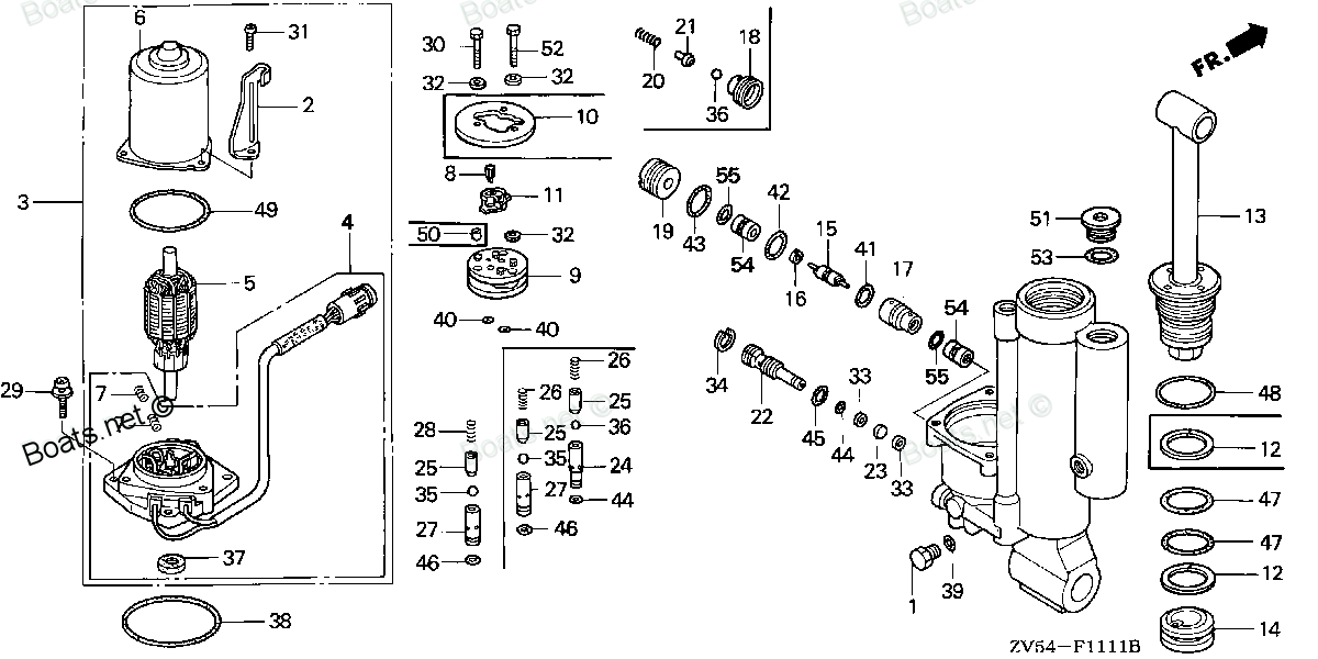
90001-ZV5-821 SCREW-WASHER (Honda Code 4594701). Honda
BF35AM LRTA, BF35AM XRTA, BF40A1 LHTA, BF40A1 LRTA, BF40A1 XRTA, BF40A2 LHTA, BF40A2 LRTA, BF40A2 XRTA, BF40AW LHTA, BF40AW LRTA, BF40AW XRTA, BF40AX LHTA, BF40AX LRTA, BF40AX XRTA, BF40AY LHTA, BF40AY LRTA, BF40AY XRTA, BF45AM LRTA, BF45AM SRTA, BF4
SCREW
. Honda parts")
Price: query
Rating:
You can buy parts:
As an associate, we earn commssions on qualifying purchases through the links below

$16.46
05-07-2024
0.25[0.11] pounds
US: PowerToolReplacement
Honda 90001-ZV5-821 Screw-Washer
Honda Honda 90001-ZV5-821 Screw-Washer
Honda Honda 90001-ZV5-821 Screw-Washer
Number on catalog scheme: 29
Compatible models:
BF35AM LRTA
BF35AM XRTA
BF40A1 LHTA
BF40A1 LRTA
BF40A1 XRTA
BF40A2 LHTA
BF40A2 LRTA
BF40A2 XRTA
BF40AW LHTA
BF40AW LRTA
BF40AW XRTA
BF40AX LHTA
BF40AX LRTA
BF40AX XRTA
BF40AY LHTA
BF40AY LRTA
BF40AY XRTA
BF45AM LRTA
BF45AM SRTA
BF45AM XRTA
BF50A1 LHTA
BF50A1 LRTA
BF50A1 XRTA
BF50A2 LHTA
BF50A2 LRTA
BF50A2 XRTA
BF50AW LHTA
BF50AW LRTA
BF50AW XRTA
BF50AX LHTA
BF50AX LRTA
BF50AX XRTA
BF50AY LHTA
BF50AY LRTA
BF50AY XRTA
Honda
Honda entire parts catalog list:
- POWER TILT COMPONENTS » 90001-ZV5-821
- POWER TILT COMPONENTS » 90001-ZV5-821
- POWER TRIM-TILT » 90001-ZV5-821
- POWER TRIM-TILT » 90001-ZV5-821
- POWER TRIM-TILT » 90001-ZV5-821
- POWER TRIM-TILT » 90001-ZV5-821
- POWER TRIM-TILT » 90001-ZV5-821
- POWER TRIM-TILT » 90001-ZV5-821
- POWER TILT COMPONENTS » 90001-ZV5-821
- POWER TILT COMPONENTS » 90001-ZV5-821
- POWER TILT COMPONENTS » 90001-ZV5-821
- POWER TILT COMPONENTS » 90001-ZV5-821
- POWER TILT COMPONENTS » 90001-ZV5-821
- POWER TILT COMPONENTS » 90001-ZV5-821
- POWER TRIM-TILT » 90001-ZV5-821
- POWER TRIM-TILT » 90001-ZV5-821
- POWER TRIM-TILT » 90001-ZV5-821
- POWER TILT COMPONENTS » 90001-ZV5-821
- POWER TILT COMPONENTS » 90001-ZV5-821
- POWER TILT COMPONENTS » 90001-ZV5-821
- POWER TRIM-TILT » 90001-ZV5-821
- POWER TRIM-TILT » 90001-ZV5-821
- POWER TRIM-TILT » 90001-ZV5-821
- POWER TRIM-TILT » 90001-ZV5-821
- POWER TRIM-TILT » 90001-ZV5-821
- POWER TRIM-TILT » 90001-ZV5-821
- POWER TILT COMPONENTS » 90001-ZV5-821
- POWER TILT COMPONENTS » 90001-ZV5-821
- POWER TILT COMPONENTS » 90001-ZV5-821
- POWER TILT COMPONENTS » 90001-ZV5-821
- POWER TILT COMPONENTS » 90001-ZV5-821
- POWER TILT COMPONENTS » 90001-ZV5-821
- POWER TRIM-TILT » 90001-ZV5-821
- POWER TRIM-TILT » 90001-ZV5-821
- POWER TRIM-TILT » 90001-ZV5-821
Information:
Table 1
Required Tools
Tool Part Number Part Description Qty
A(1) 9U-6198 Crankshaft Turning Tool 1
A(2) 9U-7336 Housing 1
5P-7305 Engine Turning Tool 1
B 136-4632 Engine Timing Pin 1
268-1966 Adaptor 1
C 364-9107 Fuel Injection Pump Timing Pin 1
(1) The Crankshaft Turning Tool is used on the front pulley.
(2) This Tool is used in the aperture for the electric starting motor.Note: Either Tooling (A) can be used. Use the Tooling that is most suitable.
Ensure that all adjustments and repairs that are carried out to the fuel system are performed by authorized personnel that have the correct training.Before beginning ANY work on the fuel system, refer to Operation and Maintenance Manual, "General Hazard Information and High Pressure Fuel Lines" for safety information. Refer to System Operation, Testing and Adjusting, "Cleanliness of Fuel System Components" for detailed information on the standards of cleanliness that must be observed during ALL work on the fuel system.
Ensure that wiring harness are correctly routed and the cable straps are not over tightened. Over tightening of the cable straps will damage the wiring harness convoluting.
Illustration 1 g01967538
If necessary, use Tooling (A) in order to rotate the crankshaft so that number one piston is at top dead center on the compression stroke. Refer to System Operation, Testing and Adjusting, "Fuel Injection Timing - Check". Use Tooling (B) in order to lock the crankshaft so that number one piston is at top dead center position.
If necessary, install Tooling (C) in order to lock the fuel injection pump in the correct position.
Position a new gasket (17) (not shown) onto front housing (16).
Position bolt (15) and spacer (14) onto fuel injection pump (10).
Carefully install fuel injection pump (10) to front housing (16). Ensure that the bore in front housing (16) is not damaged as the fuel injection pump is installed. Note: The fuel injection pump should be supported by hand as the nuts and bolts are installed.
Tighten bolt (15) for fuel injection pump (10) finger tight.
Install nut (13) to fuel injection pump (10) finger tight.
Install new bolts (17) to fuel injection pump (10) finger tight.
Tighten bolts (17) and bolts (15) to a torque of 22 N m (195 lb in). Tighten nut (13) to a torque of 22 N m (195 lb in).
Illustration 2 g01967536
Remove Tooling (C) from fuel injection pump (10). Install a new O-ring seal (9) (not shown) to plug (8).
Remove Tooling (B) from the cylinder block. Install a new O-ring seal to the plug for the cylinder block. Install the plug to the cylinder block. Tighten the plug to a torque of 21 N m (186 lb in).
Install plug (8) to fuel injection pump (10). Tighten the plug to a torque of 14 N m (124 lb in).
Remove the appropriate caps in order to install fuel injection line (11). Install a new fuel injection line (11) to the fuel injection pump and to the fuel manifold. Refer to Disassembly and Assembly, "Fuel Injection Lines - Install" for the correct procedure.
Connect harness assembly (1) to the sensor on fuel injection pump (10).
Connect harness assembly (3) from the solenoid on fuel injection pump (10).
Remove the appropriate plugs and caps in order to install plastic tube assembly (2), plastic tube assembly (4), and plastic tube assembly (5).
Connect plastic tube assembly (2), plastic tube assembly (4), and plastic tube assembly (5) to fuel injection pump (10).
Remove the appropriate plugs and caps in order to install hose assembly (12).
Install a new sealing washer (6) to banjo bolt (7). Install the banjo bolt to hose assembly (12). Install the remaining new sealing washer (6) to banjo bolt (7) after the banjo bolt is installed to the hose assembly.
Install hose assembly (12) to fuel injection pump (10) and tighten banjo bolt (7) finger tight.
Tighten banjo bolt (7) to a torque of 22 N m (195 lb in).
If necessary, install the fuel priming pump. Refer to Disassembly and Assembly, "Fuel Priming Pump - Remove and Install".
If necessary, install the fuel filter base. Refer to Disassembly and Assembly, "Fuel Filter Base - Remove and Install" for the correct procedure.
Replace the filters for primary fuel system. Refer to Operation and Maintenance Manual, "Fuel System Primary (Water Separator) Element - Replace" for the correct procedure.
Replace the filters for secondary fuel system. Refer to Operation and Maintenance Manual, "Fuel System Secondary Filter - Replace" for the correct procedure.
Turn the fuel supply to the ON position.
Turn the battery disconnect switch to the ON position.
Remove the air from the fuel system. Refer to Operation and Maintenance Manual, "Fuel System - Prime" for the correct procedure. End By:
After replacement of the fuel injection pump, the fuel injection pump requires a high-pressure fuel pump calibration procedure to be performed. Refer to Troubleshooting, "Fuel Rail Pressure Problem" for the correct procedure.
Parts screw Honda:
16071-ZV4-005

16071-ZV4-005 SCREW, PLUG (Honda Code 2794956).
BF15A1 LA, BF15A1 LAS, BF15A1 SA, BF15A1 SAS, BF15A1 XAS, BF15A2 LA, BF15A2 LAS, BF15A2 SA, BF15A2 SAS, BF15A2 XAS, BF15AM LA, BF15AM LAS, BF15AM SA, BF15AM SAS, BF15AM XAS, BF15AW LA, BF15AW LAS, BF15AW SA, BF15AW SAS, BF15AW XAS, BF15AX LA, BF15AX
16081-ZV4-650
16081-ZV4-650 SCREW-WASHER (Honda Code 3507852).
BF15A1 LA, BF15A1 LAS, BF15A1 SA, BF15A1 SAS, BF15A1 XAS, BF15A2 LA, BF15A2 LAS, BF15A2 SA, BF15A2 SAS, BF15A2 XAS, BF15AM LA, BF15AM LAS, BF15AM SA, BF15AM SAS, BF15AM XAS, BF15AW LA, BF15AW LAS, BF15AW SA, BF15AW SAS, BF15AW XAS, BF15AX LA, BF15AX
16016-ZV3-000
16016-ZV3-000 SCREW SET (Honda Code 3701752).
BF35AM LHA, BF35AM LRA, BF35AM LRTA, BF35AM SHA, BF35AM XRTA, BF45AM LHA, BF45AM LRA, BF45AM LRTA, BF45AM SRTA, BF45AM XRTA, BF75AT LHTA, BF75AT LRTA, BF75AT XRTA, BF90AT LHTA, BF90AT LRTA, BF90AT XRTA
90123-ZV3-000
90123-ZV3-000 SCREW, PAN (5X12) (Honda Code 3718723).
BF25A1 LHA, BF25A1 LHSA, BF25A1 SHA, BF25A1 SHSA, BF25A2 LHA, BF25A2 LHSA, BF25A2 SHA, BF25A2 SHSA, BF25A3 LHA, BF25A3 LHSA, BF25A3 SHA, BF25A3 SHSA, BF25AW LHA, BF25AW LHSA, BF25AW SHA, BF25AW SHSA, BF25AX LHA, BF25AX LHSA, BF25AX SHA, BF25AX SHSA,
93500-06016-0B

93500-06016-0B SCREW, PAN (6X16) (Honda Code 2088714).
BF35AM LHA, BF35AM LRA, BF35AM LRTA, BF35AM SHA, BF35AM XRTA, BF40A1 LHA, BF40A1 LHTA, BF40A1 LRA, BF40A1 LRTA, BF40A1 XRTA, BF40A2 LHA, BF40A2 LHTA, BF40A2 LRA, BF40A2 LRTA, BF40A2 XRTA, BF40AW LHA, BF40AW LHTA, BF40AW LRA, BF40AW LRTA, BF40AW XRTA,
16016-ZV7-B51
16016-ZV7-B51 SCREW SET (Honda Code 5686761).
BF25A1 LHA, BF25A1 LHSA, BF25A1 LRSA, BF25A1 SHA, BF25A1 SHSA, BF25A1 SRSA, BF25A1 XRSA, BF25A2 LRSA, BF25A2 SRSA, BF25A2 XRSA, BF25AW LHA, BF25AW LHSA, BF25AW LRSA, BF25AW SHA, BF25AW SHSA, BF25AW SRSA, BF25AW XRSA, BF25AX LHA, BF25AX LHSA, BF25AX L
16016-ZW4-D21
16016-ZW4-D21 SCREW SET (Honda Code 6652119).
BF15A1 LA, BF15A1 LAS, BF15A1 SA, BF15A1 SAS, BF15A1 XAS, BF15A2 LA, BF15A2 LAS, BF15A2 SA, BF15A2 SAS, BF15A2 XAS, BF40A4 LHA, BF40A4 LHTA, BF40A4 LRTA, BF40A5 LHA, BF40A5 LHTA, BF40A5 LRTA, BF40A6 LHA, BF40A6 LHTA, BF40A6 LRTA, BF40AK0 LHA, BF40AK0
90104-ZW7-U01
90104-ZW7-U01 SCREW, TAPPING (6X30) (Honda Code 7207475).
BF115A3 LA, BF115A3 LCA, BF115A3 XA, BF115A3 XCA, BF115A4 LA, BF115A4 LCA, BF115A4 XA, BF115A4 XCA, BF115A5 LA, BF115A5 LCA, BF115A5 XA, BF115A5 XCA, BF115A6 LA, BF115A6 LCA, BF115A6 XA, BF115A6 XCA, BF115AK0 LA, BF115AK0 XA, BF115DK1 LA, BF115DK1 XA