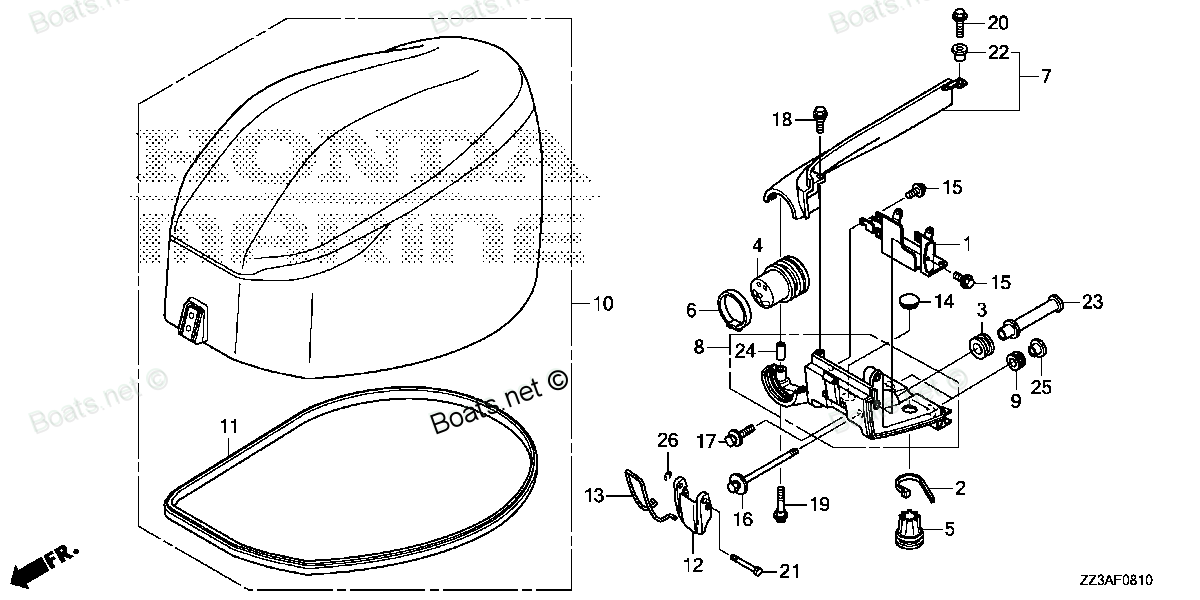
63102-ZZ3-000 SEAL, ENGINE COVER Honda
BF60AK1 LRTA, BF60AK1 XRTA, BFP60AK1 LRTA, BFP60AK1 LRTB, BFP60AK1 XRTA
SEAL

Price: query
Rating:
You can buy parts:
As an associate, we earn commssions on qualifying purchases through the links below

$37.15
25-09-2024
1.0[0.45] Pounds
US: HONDA-KTMSOUTHGA
Honda 63102-ZZ3-000 Seal, Engine Cover; 63102ZZ3000 Made by Honda
Honda New
Honda New
Number on catalog scheme: 11
Compatible models:
Honda entire parts catalog list:
- ENGINE COVER » 63102-ZZ3-000
- ENGINE COVER » 63102-ZZ3-000
- ENGINE COVER » 63102-ZZ3-000
- ENGINE COVER » 63102-ZZ3-000
- ENGINE COVER » 63102-ZZ3-000
Information:
1. Remove bolts (1) that hold the elbow in position on the oil pump. Remove bolt (2) and lock that fastens the suction bell to the oil pan plate.
The oil pump idler gear (5) can fall off the pump when the pump is removed. To prevent injury always hold gear on the pump when the pump is removed.
2. Bend the two tabs on the locks on the left hand side of the engine. Remove the four bolts (3) and (4) that fasten the oil pump to the cylinde block. Remove the oil pump and suction bell as a unit. The weight of the unit is 16 kg (35 lb.). Remove idler gear (5) from the oil pump.Install Oil Pump
1. Install idler gear (2) on the oil pump. Put the oil pump (1) in position on the cylinder block. Be sure idler gear (2) is engaged with the crankshaft gear and the tabs on locks on the left hand mounting bolts are not next to the oil pan gasket surface when the bolts are tightened. 2. Install bolts (3) that fasten the gasket and elbow to the oil pump.3. Install the lock and bolt (4) that hold the suction bell to the oil pan plate.END BY:a) install oil panDisassemble Oil Pump
START BY:a) remove oil pump 1. Remove idler gear (2). Remove bearing from gear with tooling (B).2. Remove suction bell (1).3. Remove the bolt and the washer from the oil pump drive gear. 4. Remove the drive gear from the shaft with tooling (A).5. Remove the key from the pump shaft.6. Remove bolts (3) from the pump body. 7. Remove body (8), two gears (7), keys and spacer (4) from the pump.8. Remove two shafts (5) and the gears.9. Remove bolts (6), the cover and the pressure relief valve from the body. 10. Remove the bearings from the oil pump body assembly and the scavenge pump body assembly with tooling (B). Assemble Oil Pump
1. Install the bearings in the scavenge pump body assembly with tooling (A) and a press as follows:a) Put bearings (1) in position on the inside of the scavenge pump body assembly with the chamfer on the bearing toward the outside of the pump body. Install the bearing until it is 1.52 mm (.060 in.) below the inside machined surface of the scavenge pump body assembly. Make sure the joints in the bearings are at an angle of 30° 15° from the center line through the bores in the scavenge pump body and toward the outlet passage of the pump. The outlet passage has a cavity between the bearing bores. 2. Install the bearings in oil pump body assembly with tooling (A) and a press as follows:a) Put bearings (2) in position on the inside of the oil pump body assembly with the chamfer on the bearings toward the outside of the pump body. Install the bearings until they are even with the outside of the pump body. Make sure the joints in the bearings are at an angle of 30° 15° from the centerline through the bearing bores and toward the outlet passage of the pump. The outlet passage has a cavity between the bearing bores.3. Check the condition of the relief valve. Check the condition and specifications for all the parts of the oil pump before it is assembled. See OIL PUMP in SPECIFICATIONS.4. Put clean engine oil on all the parts of the oil pump. 5. Install pressure relief valve (3), cover (4) and bolt (5) in the oil pump body assembly. 6. Install gears and shafts (6) in the oil pump body assembly.7. Install spacer (7) and the two keys in shafts (6). 8. Install two gears and scavenge pump body assembly (8).9. Install key (9), drive gear (11), the washer and bolt (10). Tighten the bolt to a torque of 43 7 N m (32 5 lb.ft.).10. Install the bearing in the idler gear with tooling (A) and a press until it is even with the outside surface of the gear.11. Install the idler gear and suction bell.
The oil pump must turn freely by hand after it is assembled.
END BY:a) install oil pump
Parts seal Honda:
91254-ZY3-003

91254-ZY3-003 SEAL, WATER (12X21X6) (Honda Code 6994503).
BF115A2 LA, BF115A2 LCA, BF115A2 XA, BF115A2 XCA, BF115A4 LA, BF115A4 XA, BF115A5 LA, BF115A5 LCA, BF115A5 XA, BF115A5 XCA, BF115A6 LA, BF115A6 LCA, BF115A6 XA, BF115A6 XCA, BF115AK0 LA, BF115AK0 XA, BF115DK1 LA, BF115DK1 XA, BF115DK1 XCA, BF130A2 LA
91255-ZY3-003
91255-ZY3-003 SEAL, WATER (14X26X8)
BF115DK1 LA, BF115DK1 XA, BF115DK1 XCA, BF135A4 LA, BF135A4 XA, BF135A4 XCA, BF135A5 LA, BF135A5 XA, BF135A5 XCA, BF135A6 LA, BF135A6 XA, BF135A6 XCA, BF135AK0 LA, BF135AK0 XA, BF135AK0 XCA, BF135AK2 LA, BF135AK2 XA, BF135AK2 XCA, BF150A4 LA, BF150A4
91252-ZW4-003

91252-ZW4-003 SEAL, WATER (22X35X7) (Honda Code 7769177).
BF25D4 LHA, BF25D4 LHTA, BF25D4 LRGA, BF25D4 LRTA, BF25D4 SHA, BF25D4 SHGA, BF25D4 SRGA, BF25D4 SRTA, BF25D5 LHA, BF25D5 LHTA, BF25D5 LRGA, BF25D5 LRTA, BF25D5 SHA, BF25D5 SHGA, BF25D5 SRGA, BF25D5 SRTA, BF25D6 LHA, BF25D6 LHTA, BF25D6 LRGA, BF25D6 L
63724-ZZ3-000
63724-ZZ3-000 SEAL, RR. COVER (LOWER)
BF60AK1 LRTA, BF60AK1 XRTA, BFP60AK1 LRTA, BFP60AK1 LRTB, BFP60AK1 XRTA
82874-ZY9-000
82874-ZY9-000 SEAL, WATER CHECK GROMMET
BF60AK1 LRTA, BF60AK1 XRTA, BF75DK0 LHTA, BF75DK0 LRTA, BF75DK2 LRTA, BF90DK0 LHTA, BF90DK0 LRTA, BF90DK0 XRTA, BF90DK2 LRTA, BF90DK2 XRTA, BFP60AK1 LRTA, BFP60AK1 LRTB, BFP60AK1 XRTA
63719-ZZ3-000
63719-ZZ3-000 SEAL B, COVER (LOWER)
BF60AK1 LRTA, BF60AK1 XRTA, BFP60AK1 LRTA, BFP60AK1 LRTB, BFP60AK1 XRTA
91251-ZZ3-003
91254-ZZ3-003
