56172-ZV5-821 SEAT, PLATE (Honda Code 4594644). Honda
BF35AM LRTA, BF35AM XRTA, BF40AW LHTA, BF40AW LRTA, BF40AW XRTA, BF45AM LRTA, BF45AM SRTA, BF45AM XRTA, BF50AW LHTA, BF50AW LRTA, BF50AW XRTA
SEAT
. Honda parts")
Price: query
Rating:
Number on catalog scheme: 23
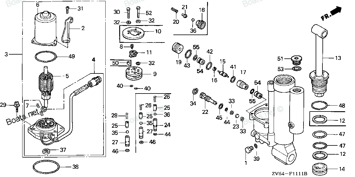
Compatible models:
Honda entire parts catalog list:
- POWER TILT COMPONENTS » 56172-ZV5-821
- POWER TILT COMPONENTS » 56172-ZV5-821
- POWER TILT COMPONENTS » 56172-ZV5-821
- POWER TILT COMPONENTS » 56172-ZV5-821
- POWER TILT COMPONENTS » 56172-ZV5-821
- POWER TILT COMPONENTS » 56172-ZV5-821
- POWER TILT COMPONENTS » 56172-ZV5-821
- POWER TILT COMPONENTS » 56172-ZV5-821
- POWER TILT COMPONENTS » 56172-ZV5-821
- POWER TILT COMPONENTS » 56172-ZV5-821
- POWER TILT COMPONENTS » 56172-ZV5-821
Information:
Table 1
Required Tools
Tool Part Number Part Description Qty
B 276-1216 Injector Pipe Nut Tool 1
Ensure that all adjustments and repairs that are carried out to the fuel system are performed by authorized personnel that have the correct training.Before beginning ANY work on the fuel system, refer to Operation and Maintenance Manual, "General Hazard Information and High-Pressure Fuel Lines" for safety information.Refer to System Operation, Testing and Adjusting, "Cleanliness of Fuel System Components" for detailed information on the standards of cleanliness that must be observed during ALL work on the fuel system.
Note: The following procedure should be adopted to install the fuel injection lines when the electronic unit injectors or the fuel manifold have not been removed. If the electronic unit injectors or the fuel manifold have been removed, refer to Disassembly and Assembly, "Electronic Unit Injector - Install" and Disassembly and Assembly, "Fuel Manifold - Install" for more information.
Ensure that wiring harness are correctly routed and the cable straps are not over tightened. Over tightening of the cable straps will damage the wiring harness convoluting.
Illustration 1 g02177629
Remove plugs from fuel manifold (16) and fuel injection pump (23).
Remove the caps from new fuel injection line (22).
Position fuel injection line (22) onto fuel injection pump (23) and fuel manifold (16). Loosely install nuts for the fuel injection line onto the fuel manifold and the fuel injection pump.
Install bolt (24) and bolt (25) to the tube clip finger tight.
Use Tooling (B) to tighten the nuts on fuel injection line (22) to a torque of 55 N m (41 lb ft).
Tighten bolt (24) and bolt (25) to a torque of 10 N m (88 lb in).Note: Ensure that fuel injection lines do not contact any other engine component.
Illustration 2 g02177712
Illustration 3 g02177628
Follow Step 7 through Step 15 to install fuel injection lines for number one cylinder to number three cylinder.
Install new seal (20) to the electronic unit injector and cylinder head (21). Ensure that the flange on the seal is flush with the cylinder head.
Remove the caps from the port of the electronic unit injector and from the appropriate port in fuel manifold (16).
Loosely connect the nuts at both ends of fuel injection line (12) to the electronic unit injector and to the appropriate port in fuel manifold (16). Ensure that the ends of the fuel injection line are correctly seated in the electronic unit injector and in the fuel manifold.
If no further fuel injection lines are to be installed, follow Step 11.a through Step 11.e to assemble clamp (13) and clamp (15) for the fuel injection lines.
Position rubber separator (25) onto the fuel injection lines.
Position clamp (13) and install bolt (14) finger tight.
Tighten bolt (24) and bolt (22) finger tight.
Illustration 4 g02178062
Ensure that dust seal (27) is seated correctly against seal (20).
Use a suitable tool to install tube clamp (15) to fuel injection lines (12).Note: Ensure that the rubber separator is correctly installed to the fuel injection lines. Ensure that the fuel injection lines do not contact any other engine component.
Use Tooling (B) to tighten the nuts on fuel injection line (22) to a torque of 55 N m (41 lb ft).
Follow Step 8 through Step 12 to install the remaining fuel injection lines.
Tighten bolt (14) and bolt (24) for tube clamp (13) to a torque of 10 N m (88 lb in).
Tighten bolt (22) to a torque of 22 N m (195 lb in).
Follow Step 17 through Step 23 to install fuel injection lines for number four cylinder to number six cylinder.
Install new seal (20) to the electronic unit injector and cylinder head (21). Ensure that the flange on the seal is flush with the cylinder head.
Remove the caps from the port of the electronic unit injector and from the appropriate port in fuel manifold (16).
Loosely connect the nuts at both ends of fuel injection line (19) to the electronic unit injector and to the appropriate port in fuel manifold (16). Ensure that the ends of the fuel injection line are correctly seated in the electronic unit injector and in the fuel manifold.
If no further fuel injection lines are to be installed, follow Step 20.a through Step 20.d to assemble clamp (17) for the fuel injection lines.
Position rubber separator (26) onto the fuel injection lines.
Position clamp (17) and install bolt (18) finger tight.
Tighten bolt (23) finger tight.Note: Ensure that the rubber separator is correctly installed to the fuel injection lines. Ensure that the fuel injection lines do not contact any other engine component.
Illustration 5 g02178062
Ensure that dust seal (27) is seated correctly against seal (20).
Use Tooling (B) to tighten the nuts on fuel injection line (22) to a torque of 55 N m (41 lb ft).
Follow Step 17 through Step 23 to install the remaining fuel injection lines.
Tighten bolt (23) and bolt (18) for tube clamp (17) to a torque of 10 N m (88 lb in).Note: Ensure that the rubber separator is correctly installed to the fuel injection lines.
Illustration 6 g02358237
Position a new gasket (11) onto the cylinder head.
P
Parts seat Honda:
19272-881-810

19272-881-810 SEAT, WATER MOUTH (Honda Code 1541150).
BF115A1 LA, BF115A1 LCA, BF115A1 XA, BF115A1 XCA, BF115A2 LA, BF115A2 LCA, BF115A2 XA, BF115A2 XCA, BF115A3 LA, BF115A3 LCA, BF115A3 XA, BF115A3 XCA, BF115A4 LA, BF115A4 LCA, BF115A4 XA, BF115A4 XCA, BF115A5 LA, BF115A5 LCA, BF115A5 XA, BF115A5 XCA,
14775-ZV5-000
14775-ZV5-000 SEAT, VALVE SPRING (Honda Code 3701638).
BF35AM LHA, BF35AM LRA, BF35AM LRTA, BF35AM SHA, BF35AM XRTA, BF40A1 LHA, BF40A1 LHTA, BF40A1 LRA, BF40A1 LRTA, BF40A1 XRTA, BF40A2 LHA, BF40A2 LHTA, BF40A2 LRA, BF40A2 LRTA, BF40A2 XRTA, BF40A3 LHA, BF40A3 LHTA, BF40A3 LRA, BF40A3 LRTA, BF40A3 XRTA,
56162-ZV5-821
56162-ZV5-821 SEAT D, VALVE (Honda Code 4594594).
BF35AM LRTA, BF35AM XRTA, BF40AW LHTA, BF40AW LRTA, BF40AW XRTA, BF45AM LRTA, BF45AM SRTA, BF45AM XRTA, BF50AW LHTA, BF50AW LRTA, BF50AW XRTA
56181-ZV5-821

56181-ZV5-821 SEAT, VALVE (Honda Code 4594651).
BF35AM LRTA, BF35AM XRTA, BF40AW LHTA, BF40AW LRTA, BF40AW XRTA, BF45AM LRTA, BF45AM SRTA, BF45AM XRTA, BF50AW LHTA, BF50AW LRTA, BF50AW XRTA
56191-ZV5-821
56191-ZV5-821 SEAT B, VALVE (Honda Code 4594685).
BF35AM LRTA, BF35AM XRTA, BF40AW LHTA, BF40AW LRTA, BF40AW XRTA, BF45AM LRTA, BF45AM SRTA, BF45AM XRTA, BF50AW LHTA, BF50AW LRTA, BF50AW XRTA
56191-ZV5-822
56191-ZV5-822 SEAT B, VALVE (Honda Code 6013007).
BF40A1 LHTA, BF40A1 LRTA, BF40A1 XRTA, BF40A2 LHTA, BF40A2 LRTA, BF40A2 XRTA, BF40A3 LHTA, BF40A3 LRTA, BF40A3 XRTA, BF40AW LHTA, BF40AW LRTA, BF40AX LHTA, BF40AX LRTA, BF40AX XRTA, BF40AY LHTA, BF40AY LRTA, BF40AY XRTA, BF50A1 LHTA, BF50A1 LRTA, BF5