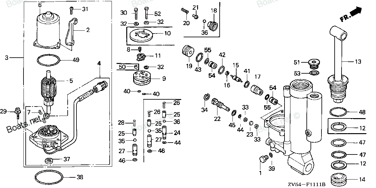
56181-ZV5-821 SEAT, VALVE (Honda Code 4594651). Honda
BF35AM LRTA, BF35AM XRTA, BF40AW LHTA, BF40AW LRTA, BF40AW XRTA, BF45AM LRTA, BF45AM SRTA, BF45AM XRTA, BF50AW LHTA, BF50AW LRTA, BF50AW XRTA
SEAT
. Honda parts")
Price: query
Rating:
You can buy parts:
As an associate, we earn commssions on qualifying purchases through the links below

$64.26
29-04-2024
0.01[0.00] pounds
US: PowerToolReplacement
Honda 56181-ZV5-821 Seat Valve
Honda Genuine, OEM Honda Replacement Part || Honda replacement valve seat, part number 56181-ZV5-821
Honda Genuine, OEM Honda Replacement Part || Honda replacement valve seat, part number 56181-ZV5-821
Number on catalog scheme: 24
Compatible models:
Honda entire parts catalog list:
- POWER TILT COMPONENTS » 56181-ZV5-821
- POWER TILT COMPONENTS » 56181-ZV5-821
- POWER TILT COMPONENTS » 56181-ZV5-821
- POWER TILT COMPONENTS » 56181-ZV5-821
- POWER TILT COMPONENTS » 56181-ZV5-821
- POWER TILT COMPONENTS » 56181-ZV5-821
- POWER TILT COMPONENTS » 56181-ZV5-821
- POWER TILT COMPONENTS » 56181-ZV5-821
- POWER TILT COMPONENTS » 56181-ZV5-821
- POWER TILT COMPONENTS » 56181-ZV5-821
- POWER TILT COMPONENTS » 56181-ZV5-821
Information:
Sulfuric Acid Burn Hazard may cause serious personal injury or death.The exhaust gas cooler may contain a small amount of sulfuric acid. The use of fuel with sulfur levels greater than 15 ppm may increase the amount of sulfuric acid formed. The sulfuric acid may spill from the cooler during service of the engine. The sulfuric acid will burn the eyes, skin and clothing on contact. Always wear the appropriate personal protective equipment (PPE) that is noted on a material safety data sheet (MSDS) for sulfuric acid. Always follow the directions for first aid that are noted on a material safety data sheet (MSDS) for sulfuric acid.
Note: Plug or cap all open ports with new plugs or caps.
Drain the coolant from the cooling system into a suitable container for storage or disposal. Refer to Operation and Maintenance Manual, "Cooling System Coolant - Change" for the correct procedure.
Illustration 1 g03456296
Cut cable straps (7) and cable strap (8). Note: Note the position of cable straps and the type of cable straps.
Remove bolts (2) and position the bracket away from tube assembly (3).
Remove bolts (10) from tube assembly (3). Remove the tube assembly from NRS exhaust cooler (6) and the cylinder head.
Remove gasket (1) (not shown) and gasket (10) (not shown).
Remove bolts (5) from tube assembly (4).
Illustration 2 g02176882
Typical example
Remove bolt (12) from clip for the tube assembly.
Loosen bolts (11) for the support bracket. Remove bolts (14) and bolts (33). Remove tube assembly (15) from the NRS exhaust cooler.
Remove gasket (13) (not shown) and gasket (34) (not shown).
Remove bolts (17) and bolts (31). Remove tube assembly (16) from the NRS exhaust cooler and from the cylinder head.
Remove gasket (18) (not shown) and gasket (32) (not shown).
Remove banjo bolt (20) from tube assembly (21). Remove sealing washers (19) (not shown).
Remove bolt (25) from clip for tube assembly (21).
Remove banjo bolt (26) and remove sealing washers (27) (not shown).
Remove tube assembly (21) from the turbocharger.
Remove bolts (24) and bolts (29) from tube assembly (23).
Remove tube assembly (23). Remove gasket (22) (not shown) and gasket (30) (not shown).
Illustration 3 g02358245
Remove bolts (36) and bolts (37) from NRS exhaust cooler (6). Note: Support the weight of the NRS exhaust cooler as the bolts are removed. Note the position of different length bolts.
Remove NRS exhaust cooler (6) from the cylinder block.
Remove gasket (35) (not shown).
Illustration 4 g02176910
Remove bolts (40) from exhaust manifold (38).
Remove tube assembly (4) and remove gasket (39) (not shown). Installation Procedure
Ensure that wiring harness are correctly routed and the cable straps are not over tightened. Over tightening of the cable straps will damage the wiring harness convoluting.
Ensure that the NRS exhaust cooler is clean and free from restriction. Ensure that the NRS exhaust cooler is free from wear and damage. If necessary, replace any components that are worn or damaged. Note: The NRS exhaust cooler should not be disassembled.
Illustration 5 g02176910
Illustration 6 g02358246
Position a new gasket (39) (not shown) onto a new tube assembly (4).
Position tube assembly (4) onto exhaust manifold (38). Install new bolts (40) and tighten the bolts ensuring that the tube assembly can still move.
Position a new gasket (35) (not shown) onto tube assembly (4).
Position NRS exhaust cooler (6) onto the cylinder block. Install bolts (36) and bolts (37) to NRS exhaust cooler (6). Hand tighten bolts (36) and bolts (37). Note: The NRS exhaust cooler should be supported as the bolts are installed.
Install new bolts (7) to tube assembly (4) and tighten bolts hand tight.
Tighten bolts (36) and bolts (37) to a torque of 44 N m (32 lb ft).
Tighten bolt (7) and bolts (40) to a torque of 22 N m (195 lb in).
Illustration 7 g02176882
Typical example
Position a new gasket (18) (not shown) and a new gasket (32) (not shown) onto tube assembly (16).
Position tube assembly (16) onto the NRS exhaust cooler and the cylinder head. Install bolts (17) and bolts (31) hand tight.
Tighten bolts (17) to a torque of 22 N m (195 lb in). Tighten bolts (31) to a torque of 18 N m (159 lb in).
Ensure that tube assembly (16) is not stressed as the bolts are tightened.
Position a new gasket (13) (not shown) onto Induction mixer. Note: Ensure that the gasket is correctly installed onto location pins on the Induction mixer.
Position a new gasket (34) (not shown) onto tube assembly (15).
Position tube assembly (15) between the bracket and Induction mixer and Install bolts (14) finger tight.
Position tube assembly (15) onto the NRS exhaust cooler. Install bolts (33) finger tight.
Install bolts (12) finger tight to clip for tube assembly.
Tighten bolts (33)
Parts seat Honda:
19272-881-810

19272-881-810 SEAT, WATER MOUTH (Honda Code 1541150).
BF115A1 LA, BF115A1 LCA, BF115A1 XA, BF115A1 XCA, BF115A2 LA, BF115A2 LCA, BF115A2 XA, BF115A2 XCA, BF115A3 LA, BF115A3 LCA, BF115A3 XA, BF115A3 XCA, BF115A4 LA, BF115A4 LCA, BF115A4 XA, BF115A4 XCA, BF115A5 LA, BF115A5 LCA, BF115A5 XA, BF115A5 XCA,
14775-ZV5-000
14775-ZV5-000 SEAT, VALVE SPRING (Honda Code 3701638).
BF35AM LHA, BF35AM LRA, BF35AM LRTA, BF35AM SHA, BF35AM XRTA, BF40A1 LHA, BF40A1 LHTA, BF40A1 LRA, BF40A1 LRTA, BF40A1 XRTA, BF40A2 LHA, BF40A2 LHTA, BF40A2 LRA, BF40A2 LRTA, BF40A2 XRTA, BF40A3 LHA, BF40A3 LHTA, BF40A3 LRA, BF40A3 LRTA, BF40A3 XRTA,
56162-ZV5-821
56162-ZV5-821 SEAT D, VALVE (Honda Code 4594594).
BF35AM LRTA, BF35AM XRTA, BF40AW LHTA, BF40AW LRTA, BF40AW XRTA, BF45AM LRTA, BF45AM SRTA, BF45AM XRTA, BF50AW LHTA, BF50AW LRTA, BF50AW XRTA
56172-ZV5-821
56172-ZV5-821 SEAT, PLATE (Honda Code 4594644).
BF35AM LRTA, BF35AM XRTA, BF40AW LHTA, BF40AW LRTA, BF40AW XRTA, BF45AM LRTA, BF45AM SRTA, BF45AM XRTA, BF50AW LHTA, BF50AW LRTA, BF50AW XRTA
56191-ZV5-821

56191-ZV5-821 SEAT B, VALVE (Honda Code 4594685).
BF35AM LRTA, BF35AM XRTA, BF40AW LHTA, BF40AW LRTA, BF40AW XRTA, BF45AM LRTA, BF45AM SRTA, BF45AM XRTA, BF50AW LHTA, BF50AW LRTA, BF50AW XRTA
56191-ZV5-822
56191-ZV5-822 SEAT B, VALVE (Honda Code 6013007).
BF40A1 LHTA, BF40A1 LRTA, BF40A1 XRTA, BF40A2 LHTA, BF40A2 LRTA, BF40A2 XRTA, BF40A3 LHTA, BF40A3 LRTA, BF40A3 XRTA, BF40AW LHTA, BF40AW LRTA, BF40AX LHTA, BF40AX LRTA, BF40AX XRTA, BF40AY LHTA, BF40AY LRTA, BF40AY XRTA, BF50A1 LHTA, BF50A1 LRTA, BF5