06115-ZW5-010 SEE PART DETAILS - SUP; GASKET KIT (Honda Code 6781504). (SHORT BLOCK, HEAD ASSY.) Honda
BF115A1 LA, BF115A1 LCA, BF115A1 XA, BF115A1 XCA, BF115A2 LA, BF115A2 LCA, BF115A2 XA, BF115A2 XCA, BF115AX LA, BF115AX LCA, BF115AX XA, BF115AX XCA, BF115AY LA, BF115AY LCA, BF115AY XA, BF115AY XCA, BF130A1 LA, BF130A1 LCA, BF130A1 XA, BF130A1 XCA,
SEE
. (SHORT BLOCK, HEAD ASSY.) Honda parts")
Price: query
Rating:
Number on catalog scheme: 1
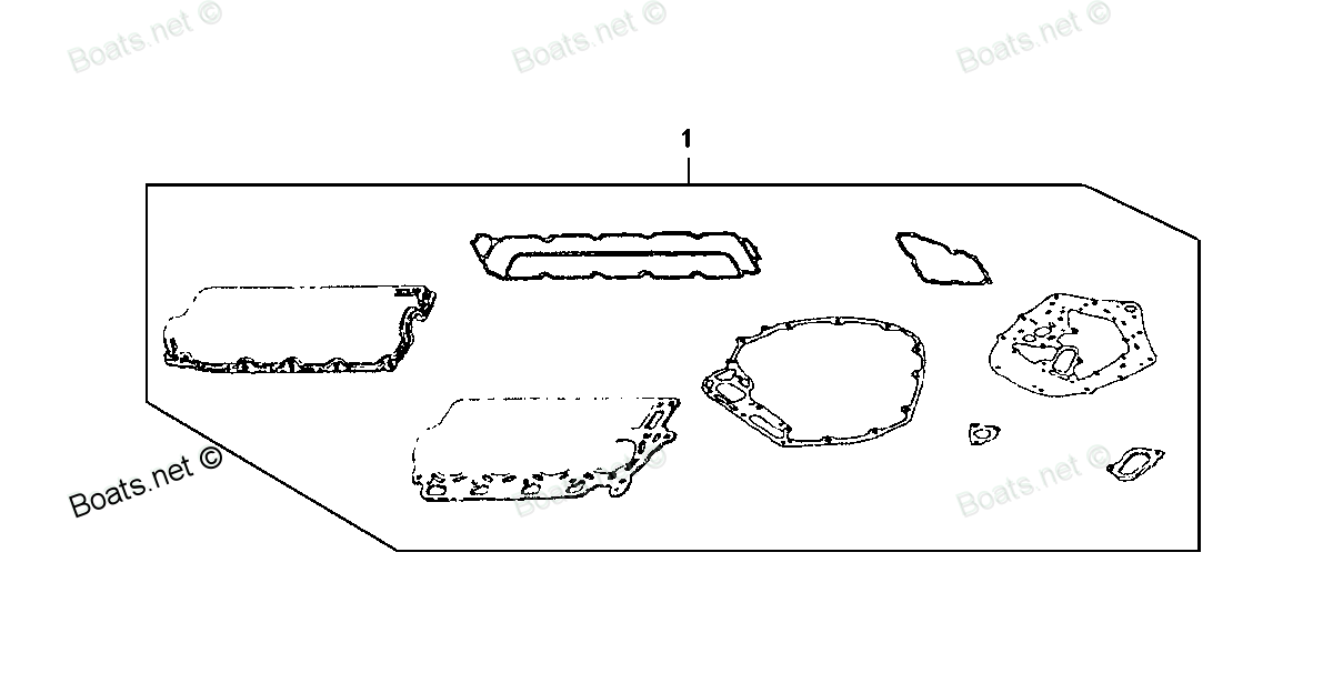
Compatible models:
BF115A1 LA
BF115A1 LCA
BF115A1 XA
BF115A1 XCA
BF115A2 LA
BF115A2 LCA
BF115A2 XA
BF115A2 XCA
BF115AX LA
BF115AX LCA
BF115AX XA
BF115AX XCA
BF115AY LA
BF115AY LCA
BF115AY XA
BF115AY XCA
BF130A1 LA
BF130A1 LCA
BF130A1 XA
BF130A1 XCA
BF130A2 LA
BF130A2 LCA
BF130A2 XA
BF130A2 XCA
BF130AX LA
BF130AX LCA
BF130AX XA
BF130AX XCA
BF130AY LA
BF130AY LCA
BF130AY XA
BF130AY XCA
Honda
Honda entire parts catalog list:
- GASKET KIT (SHORT BLOCK & HEAD ASSY.) » 06115-ZW5-010
- GASKET KIT (SHORT BLOCK & HEAD ASSY.) » 06115-ZW5-010
- GASKET KIT (SHORT BLOCK & HEAD ASSY.) » 06115-ZW5-010
- GASKET KIT (SHORT BLOCK & HEAD ASSY.) » 06115-ZW5-010
- GASKET KIT (SHORT BLOCK & HEAD ASSY.) » 06115-ZW5-010
- GASKET KIT (SHORT BLOCK & HEAD ASSY.) » 06115-ZW5-010
- GASKET KIT (SHORT BLOCK & HEAD ASSY.) » 06115-ZW5-010
- GASKET KIT (SHORT BLOCK & HEAD ASSY.) » 06115-ZW5-010
- GASKET KIT (SHORT BLOCK & HEAD ASSY.) » 06115-ZW5-010
- GASKET KIT (SHORT BLOCK & HEAD ASSY.) » 06115-ZW5-010
- GASKET KIT (SHORT BLOCK & HEAD ASSY.) » 06115-ZW5-010
- GASKET KIT (SHORT BLOCK & HEAD ASSY.) » 06115-ZW5-010
- GASKET KIT (SHORT BLOCK & HEAD ASSY.) » 06115-ZW5-010
- GASKET KIT (SHORT BLOCK & HEAD ASSY.) » 06115-ZW5-010
- GASKET KIT (SHORT BLOCK & HEAD ASSY.) » 06115-ZW5-010
- GASKET KIT (SHORT BLOCK & HEAD ASSY.) » 06115-ZW5-010
- GASKET KIT (SHORT BLOCK & HEAD ASSY.) » 06115-ZW5-010
- GASKET KIT (SHORT BLOCK & HEAD ASSY.) » 06115-ZW5-010
- GASKET KIT (SHORT BLOCK & HEAD ASSY.) » 06115-ZW5-010
- GASKET KIT (SHORT BLOCK & HEAD ASSY.) » 06115-ZW5-010
- GASKET KIT (SHORT BLOCK & HEAD ASSY.) » 06115-ZW5-010
- GASKET KIT (SHORT BLOCK & HEAD ASSY.) » 06115-ZW5-010
- GASKET KIT (SHORT BLOCK & HEAD ASSY.) » 06115-ZW5-010
- GASKET KIT (SHORT BLOCK & HEAD ASSY.) » 06115-ZW5-010
- GASKET KIT (SHORT BLOCK & HEAD ASSY.) » 06115-ZW5-010
- GASKET KIT (SHORT BLOCK & HEAD ASSY.) » 06115-ZW5-010
- GASKET KIT (SHORT BLOCK & HEAD ASSY.) » 06115-ZW5-010
- GASKET KIT (SHORT BLOCK & HEAD ASSY.) » 06115-ZW5-010
- GASKET KIT (SHORT BLOCK & HEAD ASSY.) » 06115-ZW5-010
- GASKET KIT (SHORT BLOCK & HEAD ASSY.) » 06115-ZW5-010
- GASKET KIT (SHORT BLOCK & HEAD ASSY.) » 06115-ZW5-010
- GASKET KIT (SHORT BLOCK & HEAD ASSY.) » 06115-ZW5-010
Information:
Illustration 1 g03792595
(3) Rear coverRemove the rear cover (3) to access the diodes in the generator.Diode Removal
Use the following procedure to replace the diodes.
Illustration 2 g03792622
(4) Diode crescent assembly (5) Mounting nuts that attach the leads from the rotor to the diode crescent plates (6) Leads from the rotor that are to be disconnected (7) Mounting bolts for the diode assembly (diode wheel)Note: The diode assembly includes the varistor assembly, the diodes, diode crescent plates, and the mounting plate (diode wheel) that the diode crescents are mounted to.
Remove the mounting nuts (5) that attach the leads (6) from the main rotor to the diode assembly (4) .Note: Make sure that the diode leads (6) and assemblies (4) are appropriately labeled to ensure correct installation when installation occurs.
Remove the leads (6) .
The leads to each diode will need to be unsoldered and removed from the diodes.
Illustration 3 g03779481
Diode assembly (diode wheel) removed
Remove the bolts (7) that secure the diodes assembly (4). Remove the diodes assembly.
Illustration 4 g03792647
(9) Varistor assembly (10) Varistor assembly mounting nuts
Remove the mounting nuts (10) for the varistor assembly (9). Remove the varistor assembly. Refer to Illustration 4.
Illustration 5 g03792662
(5) Mounting nuts (10) Mounting nuts
Remove the mounting nuts (5) and (10) for the diode crescent. Remove the diode crescent assembly (4). Refer to Illustration 5.
Properly secure the diode crescent in a bench vice that provides protection on the jaws so no damage will occur to the diode crescent.
Carefully remove all of the diodes from the diode crescent.Diode Installation
Install three new diodes, of the same polarity, in the diode crescent from which the diodes were removed.Note: When one diode fails, the other two diodes are forced to operate in overload condition. The overload condition for the remaining, good diodes reduces the expected life time of the diodes. Due to the possible risk of damage to the good diodes from an overload condition, Caterpillar recommends that all of the diodes be replaced.
Install three new diodes in the other diode crescent, of the opposite polarity from what was installed in Step 1.
Illustration 6 g03794995
Typical torque wrench attachment for installing diodes
Secure all diodes by tightening the diodes with a torque wrench. The correct torque values are listed in Table 1.
Table 1
Diode base thread (mm) Torque wrench attachment dimension "X" mm (3) Diode torque (N-m)
M6 11
2 N m (1.5 lb ft)
M8 17
4 N m (3 lb ft)
M12 24
10 N m (7 lb ft)
M16 32
30 N m (22 lb ft)
( 3 ) Refer to Illustration 6.
Illustration 7 g03828015
(4) Diode crescent assembly (5) Mounting nuts that attach the leads from the rotor to the diode crescent assembly (6) Leads from the rotor that are to be disconnected (7) Mounting bolts for the diode assembly (diode wheel) (10) Mounting nuts that attach the varistor assembly and diode crescent to the diode assembly (diode wheel)
Install each of the diode crescent assemblies (4) and diode wheel, removed during the disassembly procedure. Torque the mounting nuts (5) and (10) to 11 N m (8 lb ft). Torque the mounting bolts (7) to 11 N m (8 lb ft).
Connect all of the leads from the exciter rotor to the appropriate diode.Note: The leads to the diodes must be soldered at the diode connection point with a 130 W soldering iron.Note: Care must be taken to not over heat the diodes and thus damage the diode or other components while soldering.
Parts see Honda:
16957-ZE1-812

16957-ZE1-812 SEE PART DETAILS - PRI; GASKET, VALVE (Honda Code 3440708).
BF2.3DK2 LCHA, BF2.3DK2 SCHA, BF2AM SA, BF2AM SAB, BF2AW LA, BF2AW SA, BF2AW SAB, BF2D1 LCHA, BF2D1 SA, BF2D1 SAB, BF2D1 SCAB, BF2D1 SCHA, BF2D1 SHA, BF2D2 LCHA, BF2D2 SA, BF2D2 SAB, BF2D2 SCAB, BF2D2 SCHA, BF2D2 SHA, BF2D3 LCHA, BF2D3 SA, BF2D3 SAB,
95700-06012-00
95700-06012-00 SEE PART DETAILS - SUP; BOLT, FLANGE (6X12) (Honda Code 0487025).
BF2AM SA, BF5AM LA, BF5AM SA
94101-06800

94101-06800 SEE PART DETAILS - PRI; WASHER, PLAIN (6MM) (Honda Code 0345900).
BF2AM SA, BF2AM SAB, BF2AW LA, BF2AW SA, BF2AW SAB
90014-ZV1-010

90014-ZV1-010 SEE PART DETAILS - PRI; BOLT, FLANGE (5X22) (Honda Code 7496573).
BF15A1 LA, BF15A1 SA, BF15A2 LA, BF15A2 SA, BF15AM LA, BF15AM SA, BF15AW LA, BF15AW SA, BF15AX LA, BF15AX SA, BF15AY LA, BF15AY SA, BF25A1 LHA, BF25A1 SHA, BF25A2 LHA, BF25A2 SHA, BF25A3 LHA, BF25A3 SHA, BF25D4 LHA, BF25D4 SHA, BF25D5 LHA, BF25D5 SHA
87121-ZV1-C00

87121-ZV1-C00 SEE PART DETAILS - SUP; MARK, RR. (Honda Code 3747177).
BF5AM LA, BF5AM SA, BF5AX LA, BF5AX SA
19210-881-A01

19210-881-A01 SEE PART DETAILS - SUP; IMPELLER, PUMP (Honda Code 3739604).
BF5AM LA, BF5AM SA, BF5AX LA, BF5AX SA, BF8AM LA, BF8AM SA, BF8AM XA, BF8AX LA, BF8AX SA, BF8AX XA
87538-ZW1-740
87538-ZW1-740 SEE PART DETAILS - PRI; LABEL, CAUTION OPERATOR (Honda Code 4948014). (ENGLISH)
BF15D3 LGA, BF15D3 LHA, BF15D3 LHGA, BF15D3 LHSA, BF15D3 LHTA, BF15D3 LRA, BF15D3 LRTA, BF15D3 SHA, BF15D3 SHGA, BF15D3 SHSA, BF15D3 SHTA, BF15D3 SRTA, BF15D3 XHA, BF15D3 XHGA, BF15D4 LGA, BF15D4 LHA, BF15D4 LHGA, BF15D4 LHSA, BF15D4 LHTA, BF15D4 LRA
11381-ZV4-610
11381-ZV4-610 SEE PART DETAILS - PRI; GASKET, OIL PAN (Honda Code 4537502).
BF15A1 LA, BF15A1 LAS, BF15A1 SA, BF15A1 SAS, BF15A1 XAS, BF15A2 LA, BF15A2 LAS, BF15A2 SA, BF15A2 SAS, BF15A2 XAS, BF15AM LA, BF15AM LAS, BF15AM SA, BF15AM SAS, BF15AM XAS, BF15AW LA, BF15AW LAS, BF15AW SA, BF15AW SAS, BF15AW XAS, BF15AX LA, BF15AX