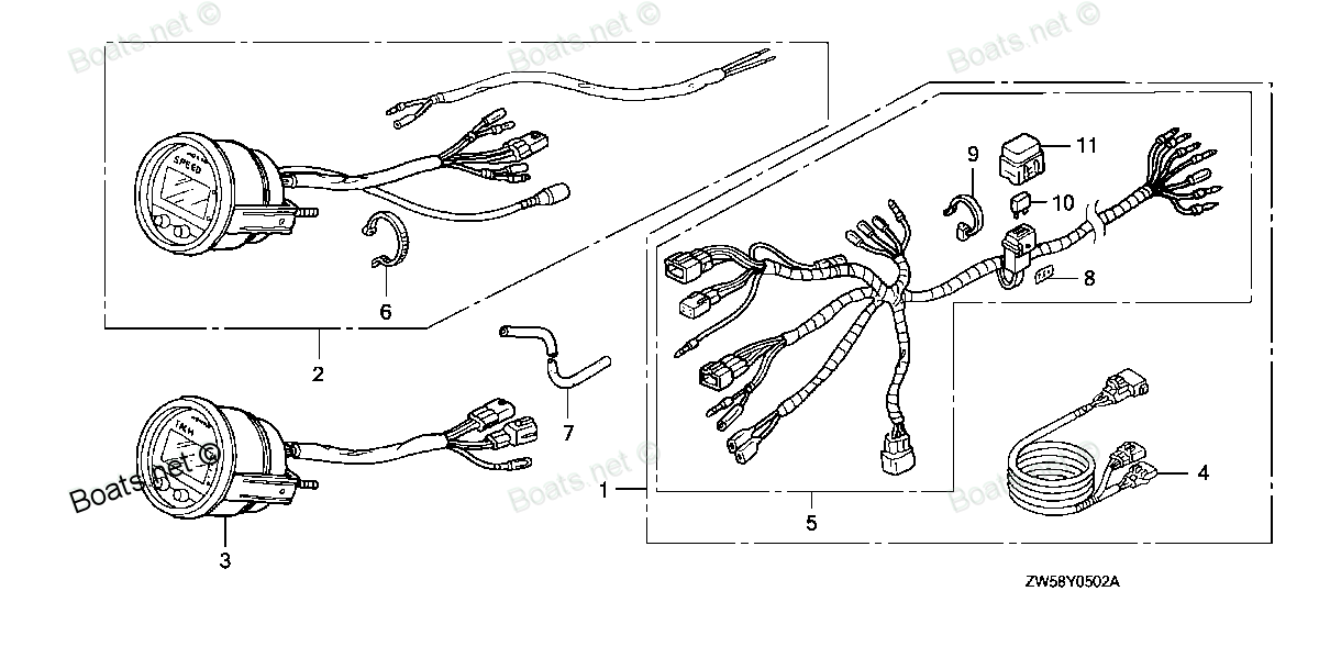
06326-ZY3-801 SEE PART DETAILS - SUP; HARNESS KIT, METER (DIGITAL) (Honda Code 7899297). (INCLUDE 32540-ZY3-801) Honda
BF115A4 LA, BF115A4 XA, BF115A5 LA, BF115A5 LCA, BF115A5 XA, BF115A5 XCA, BF115A6 LA, BF115A6 LCA, BF115A6 XA, BF115A6 XCA, BF115AK0 LA, BF115AK0 XA, BF130A4 LA, BF130A4 LCA, BF130A4 XA, BF130A4 XCA, BF135A4 LA, BF135A4 XA, BF135A4 XCA, BF135A5 LA, B
SEE
 (Honda Code 7899297). (INCLUDE 32540-ZY3-801) Honda parts")
Price: query
Rating:
Number on catalog scheme: 1
Compatible models:
BF115A4 LA
BF115A4 XA
BF115A5 LA
BF115A5 LCA
BF115A5 XA
BF115A5 XCA
BF115A6 LA
BF115A6 LCA
BF115A6 XA
BF115A6 XCA
BF115AK0 LA
BF115AK0 XA
BF130A4 LA
BF130A4 LCA
BF130A4 XA
BF130A4 XCA
BF135A4 LA
BF135A4 XA
BF135A4 XCA
BF135A5 LA
BF135A5 XA
BF135A5 XCA
BF135A6 LA
BF135A6 XA
BF135A6 XCA
BF135AK0 LA
BF135AK0 XA
BF135AK0 XCA
BF150A4 LA
BF150A4 XA
BF150A4 XCA
BF150A5 LA
BF150A5 XA
BF150A5 XCA
BF150A6 LA
BF150A6 XA
BF150A6 XCA
BF150AK0 LA
BF150AK0 XA
BF150AK0 XCA
BF200A4 LA
BF200A4 XA
BF200A4 XCA
BF200A4 XXA
BF200A4 XXCA
BF200A5 LA
BF200A5 XA
BF200A5 XCA
BF200A5 XXA
BF200A5 XXCA
BF200A6 LA
BF200A6 XA
BF200A6 XCA
BF200A6 XXA
BF200A6 XXCA
BF200AK0 LA
BF200AK0 XA
BF200AK0 XCA
BF225A4 LA
BF225A4 XA
BF225A4 XCA
BF225A4 XXA
BF225A4 XXCA
BF225A5 LA
BF225A5 XA
BF225A5 XCA
BF225A5 XXA
BF225A5 XXCA
BF225A6 LA
BF225A6 XA
BF225A6 XCA
BF225A6 XXA
BF225A6 XXCA
BF225AK0 LA
BF225AK0 XA
BF225AK0 XCA
BF225AK0 XXA
BF225AK0 XXCA
BF75DK0 LHTA
BF75DK0 LRTA
BF90DK0 LHTA
BF90DK0 LRTA
BF90DK0 XRTA
Honda
Honda entire parts catalog list:
- METER (DIGITAL) » 06326-ZY3-801
- METER (DIGITAL) » 06326-ZY3-801
- METER (DIGITAL) » 06326-ZY3-801
- METER (DIGITAL) » 06326-ZY3-801
- METER (DIGITAL) » 06326-ZY3-801
- METER (DIGITAL) » 06326-ZY3-801
- METER (DIGITAL) » 06326-ZY3-801
- METER (DIGITAL) » 06326-ZY3-801
- METER (DIGITAL) » 06326-ZY3-801
- METER (DIGITAL) » 06326-ZY3-801
- METER (DIGITAL) » 06326-ZY3-801
- METER (DIGITAL) » 06326-ZY3-801
- METER (DIGITAL) » 06326-ZY3-801
- METER (DIGITAL) » 06326-ZY3-801
- METER (DIGITAL) » 06326-ZY3-801
- METER (DIGITAL) » 06326-ZY3-801
- METER (3) » 06326-ZY3-801
- METER (3) » 06326-ZY3-801
- METER (3) » 06326-ZY3-801
- METER (3) » 06326-ZY3-801
- METER (3) » 06326-ZY3-801
- METER (3) » 06326-ZY3-801
- METER (3) » 06326-ZY3-801
- METER (3) » 06326-ZY3-801
- METER (3) » 06326-ZY3-801
- METER (3) » 06326-ZY3-801
- METER (3) » 06326-ZY3-801
- METER (3) » 06326-ZY3-801
- METER (3) » 06326-ZY3-801
- METER (3) » 06326-ZY3-801
- METER (3) » 06326-ZY3-801
- METER (3) » 06326-ZY3-801
- METER (3) » 06326-ZY3-801
- METER (3) » 06326-ZY3-801
- METER (3) » 06326-ZY3-801
- METER (3) » 06326-ZY3-801
- METER (3) » 06326-ZY3-801
- METER (3) » 06326-ZY3-801
- METER (3) » 06326-ZY3-801
- METER (3) » 06326-ZY3-801
- METER (2) » 06326-ZY3-801
- METER (2) » 06326-ZY3-801
- METER (2) » 06326-ZY3-801
- METER (2) » 06326-ZY3-801
- METER (2) » 06326-ZY3-801
- METER (2) » 06326-ZY3-801
- METER (2) » 06326-ZY3-801
- METER (2) » 06326-ZY3-801
- METER (2) » 06326-ZY3-801
- METER (2) » 06326-ZY3-801
- METER (1) » 06326-ZY3-801
- METER (1) » 06326-ZY3-801
- METER (1) » 06326-ZY3-801
- METER (1) » 06326-ZY3-801
- METER (1) » 06326-ZY3-801
- METER (1) » 06326-ZY3-801
- METER (1) » 06326-ZY3-801
- METER (1) » 06326-ZY3-801
- METER (2) » 06326-ZY3-801
- METER (2) » 06326-ZY3-801
- METER (2) » 06326-ZY3-801
- METER (2) » 06326-ZY3-801
- METER (2) » 06326-ZY3-801
- METER (2) » 06326-ZY3-801
- METER (2) » 06326-ZY3-801
- METER (2) » 06326-ZY3-801
- METER (2) » 06326-ZY3-801
- METER (2) » 06326-ZY3-801
- METER (1) » 06326-ZY3-801
- METER (1) » 06326-ZY3-801
- METER (1) » 06326-ZY3-801
- METER (1) » 06326-ZY3-801
- METER (1) » 06326-ZY3-801
- METER (1) » 06326-ZY3-801
- METER (1) » 06326-ZY3-801
- METER (1) » 06326-ZY3-801
- METER (1) » 06326-ZY3-801
- METER (1) » 06326-ZY3-801
- SPEEDOMETER KIT (DIGITAL) » 06326-ZY3-801
- SPEEDOMETER KIT (DIGITAL) » 06326-ZY3-801
- SPEEDOMETER KIT (DIGITAL) » 06326-ZY3-801
- SPEEDOMETER KIT (DIGITAL) » 06326-ZY3-801
- SPEEDOMETER KIT (DIGITAL) » 06326-ZY3-801
Information:
Inspection points1. Main bearing installation (1) Install the upper halves of the main bearings in the cylinder block and the lower halves in the main bearing caps so lower halves in the main bearing caps so their tabs fit into the notches in the cylinder block and the main bearing caps.(2) Install the flanged bearing in the No. 3 journal.(3) Lightly lubricate the inside surfaces of the bearings with engine oil.
Installing main bearings2. Crankshaft installation (1) Clean the crankshaft with cleaning solvent and blow dry with compressed air. (2) Fasten a hoist to the crankshaft and hold it in horizontal position. Carefully put the crankshaft in position in the cylinder block.(3) Lightly lubricate the crankshaft journals with engine oil.
Installing crankshaft3. Main bearing cap installation (1) Coat the mating surfaces of the rear bearing cap and cylinder block with Three Bond 1212. (2) Install the main bearing caps in position. Make sure the number (arrow head) on the main bearing cap is toward the front of the engine.(3) Tighten the main bearing cap bolts finger tight only.
Main bearing caps installed
Install the front and rear bearing caps in position so their end faces are even with the end faces of the cylinder block.
Installing front and rear bearing caps(4) Tighten the bolts holding the main bearing caps in steps to the specified torque.
Tightening bolts holding main bearing caps(5) Make sure the crankshaft rotates freely without binding or catching.(6) Measure the end play for the crankshaft. Make reference to "End play measurement for crankshaft" (page 42). If the end play is incorrect, loosen the bolts holding the main bearing caps once and tighten them again.
Checking crankshaft for rotation4. Side seal installation (1) Coat the side seals with Three Bond 1212.(2) Insert the side seals between the cylinder block and the front and rear caps and push in them by hand as far as possible, with their rounded side toward the outside of the cylinder block.
Side seals(3) Using a flat plate, push the seals into position, taking care not to bend them.
Installing side seals5. Piston assembling to connecting rod(1) Set Piston Setting Tool (31A91-00100) (special tool) in a hydraulic press.(2) Put the connecting rod on the Tool and lubricate the bore in the rod for the piston pin with engine oil.
Connecting rod on Piston Setting Tool(3) Put the piston in position on the connecting rod, making sure the model identification on the rod is on the same side as the arrow head on the top of the piston. Put the piston pin in position.
Installing piston pin(4) Insert the push rod of the Tool into the bore in the piston for the piston pin and press the pin with the press.
Observe the indicator of the press when pressing the piston pin. If the force of the press is ready to exceed 50 kgf (110 lbf) [490 N], stop pressing the pin and check the bores in the piston and connecting rod for alignment.
Pressing piston pin(5) After assembling the piston and connecting rod, make sure the connecting rod moves freely.
Checking piston and connecting rod6. Piston ring installation Using a piston ring pliers, install the piston rings on the piston. a) The piston rings must be installed with the side that has the mark "T" toward the top of the piston.b) The oil ring must be installed with the ring end gap 180° apart from the coil spring joint.
Piston rings
Oil ring7. Piston and connecting rod installation(1) Lubricate the piston and piston rings with engine oil.(2) Move the piston rings on the piston so that the end gaps are apart from a direction parallel to, or transverse to, the piston pin. (3) Install the connecting rod bearing (upper half) to the rod, making sure the tab in the back of the bearing is in the notch of the connecting rod. (4) Turn the crankshaft until the crankpin for the piston and connecting rod to be installed is at the top center. (5) Hold the piston and connecting rod with "FRONT" mark (arrow head) on the top of the piston toward the front (timing gear case side) of the engine.
Relative location of piston ring end gaps(6) Using a piston guide (commercially available), put the piston and connecting rod into the cylinder from the top of the cylinder block.
Do not hit the piston with a hammer to install the piston and connecting rod. This will put force on the piston and connecting rod and cause damage to the piston rings and crankpin.
Installing piston and connecting rod8. Connecting rod cap installation (1) Push the piston into position until the big end of the connecting rod is put into position over the crankpin. Then turn the crankshaft 180° while pushing on the top of the piston.(2) Install the lower half of the connecting rod bearing in the connecting rod cap, making sure the tab in the back of the bearing is in the notch of the cap.(3) Install the bearing cap to the connecting rod.
Installing connecting rod cap a) Make sure the number on the cap is the same as the number on the connecting rod.b) In case of a new connecting rod having no cylinder number, install the cap to the rod with the notches on the same side. (4) Tighten the connecting rod cap nuts in steps to the specified torque. (5) Check the thrust clearance for the connecting rod big end.
Tightening connecting rod cap nuts9. Oil screen installation (1) Lay the cylinder block with the bottom (oil pan side) up.(2) Install the oil screen in position. The oil screen must be installed in position so that it is below the oil level line and away from the oil pan.
Installing oil screen10. Oil pan installation (1) Clean the mating surfaces of the oil pan and cylinder block and coat them with Three Bond 1207C.
Parts see Honda:
87538-ZW1-740

87538-ZW1-740 SEE PART DETAILS - PRI; LABEL, CAUTION OPERATOR (Honda Code 4948014). (ENGLISH)
BF15D3 LGA, BF15D3 LHA, BF15D3 LHGA, BF15D3 LHSA, BF15D3 LHTA, BF15D3 LRA, BF15D3 LRTA, BF15D3 SHA, BF15D3 SHGA, BF15D3 SHSA, BF15D3 SHTA, BF15D3 SRTA, BF15D3 XHA, BF15D3 XHGA, BF15D4 LGA, BF15D4 LHA, BF15D4 LHGA, BF15D4 LHSA, BF15D4 LHTA, BF15D4 LRA
06411-ZW1-010
06411-ZW1-010 SEE PART DETAILS - SUP; METAL KIT, ANODE (Honda Code 8159857).
BF115A1 LA, BF115A1 LCA, BF115A1 XA, BF115A1 XCA, BF115A2 LA, BF115A2 LCA, BF115A2 XA, BF115A2 XCA, BF115A3 LA, BF115A3 LCA, BF115A3 XA, BF115A3 XCA, BF115A4 LA, BF115A4 LCA, BF115A4 XA, BF115A4 XCA, BF115A5 LA, BF115A5 LCA, BF115A5 XA, BF115A5 XCA,
06240-ZW7-U00

06240-ZW7-U00 SEE PART DETAILS - PRI; BOX KIT, R. REMOTE CONTROL (Honda Code 6796163). (FLUSH MOUNT)
BF115A1 LA, BF115A1 LCA, BF115A1 XA, BF115A1 XCA, BF115A2 LA, BF115A2 LCA, BF115A2 XA, BF115A2 XCA, BF115A3 LA, BF115A3 LCA, BF115A3 XA, BF115A3 XCA, BF115A4 LA, BF115A4 LCA, BF115A4 XA, BF115A4 XCA, BF115A5 LA, BF115A5 LCA, BF115A5 XA, BF115A5 XCA,
13400-PT3-010

13400-PT3-010 SEE PART DETAILS - PRI; SHAFT, RR. BALANCER (Honda Code 3339173).
BF115A1 LA, BF115A1 LCA, BF115A1 XA, BF115A1 XCA, BF115A2 LA, BF115A2 LCA, BF115A2 XA, BF115A2 XCA, BF115A3 LA, BF115A3 LCA, BF115A3 XA, BF115A3 XCA, BF115A4 LA, BF115A4 LCA, BF115A4 XA, BF115A4 XCA, BF115A5 LA, BF115A5 LCA, BF115A5 XA, BF115A5 XCA,
12000-ZW5-020ZA

12000-ZW5-020ZA SEE PART DETAILS - PRI; BLOCK ASSY., CYLINDER *NH8* (DARK GRAY)
BF115A1 LA, BF115A1 LCA, BF115A1 XA, BF115A1 XCA, BF115A2 LA, BF115A2 LCA, BF115A2 XA, BF115A2 XCA, BF115A3 LA, BF115A3 LCA, BF115A3 XA, BF115A3 XCA, BF115A4 LA, BF115A4 LCA, BF115A4 XA, BF115A4 XCA, BF115A5 LA, BF115A5 LCA, BF115A5 XA, BF115A5 XCA,
90006-ZW5-010
90006-ZW5-010 SEE PART DETAILS - PRI; BOLT 2, STUD (10X32) (Honda Code 7207335).
BF115A1 LA, BF115A1 LCA, BF115A1 XA, BF115A1 XCA, BF115A2 LA, BF115A2 LCA, BF115A2 XA, BF115A2 XCA, BF115A3 LA, BF115A3 LCA, BF115A3 XA, BF115A3 XCA, BF115A4 LA, BF115A4 LCA, BF115A4 XA, BF115A4 XCA, BF115A5 LA, BF115A5 LCA, BF115A5 XA, BF115A5 XCA,
41161-ZW5-010
41161-ZW5-010 SEE PART DETAILS - PRI; SHAFT, PROPELLER (Honda Code 7094600).
BF115A1 LA, BF115A1 XA, BF115A2 LA, BF115A2 XA, BF115A3 LA, BF115A3 XA, BF115A4 LA, BF115A4 XA, BF115A5 LA, BF115A5 XA, BF115A6 LA, BF115A6 XA, BF115AK0 LA, BF115AK0 XA, BF115AX LA, BF115AX XA, BF115AY LA, BF115AY XA, BF130A1 LA, BF130A1 XA, BF130A2
16900-ZV5-902
16900-ZV5-902 SEE PART DETAILS - PRI; JOINT ASSY., FUEL
BF115A2 LA, BF115A2 LCA, BF115A2 XA, BF115A2 XCA, BF115A3 LA, BF115A3 XA, BF115A4 LA, BF115A4 LCA, BF115A4 XA, BF115A4 XCA, BF115A5 LA, BF115A5 LCA, BF115A5 XA, BF115A5 XCA, BF115A6 LA, BF115A6 LCA, BF115A6 XA, BF115A6 XCA, BF115AK0 LA, BF115AK0 XA,