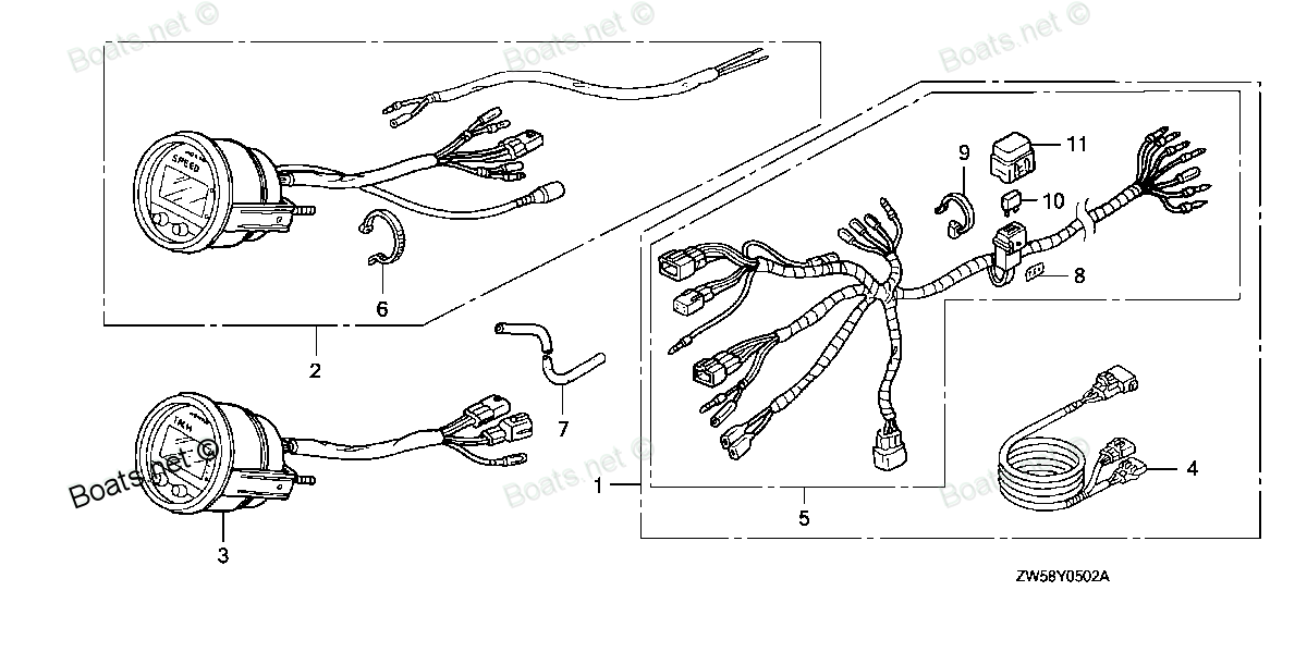
06373-ZY3-801 SEE PART DETAILS - PRI; SPEEDOMETER KIT (DIGITAL)(USA) Use from Frame SN 1500719. Honda
BF115A4 LA, BF115A4 XA, BF115A5 LA, BF115A5 LCA, BF115A5 XA, BF115A5 XCA, BF115A6 LA, BF115A6 LCA, BF115A6 XA, BF115A6 XCA, BF115AK0 LA, BF115AK0 XA, BF115DK1 LA, BF115DK1 XA, BF115DK1 XCA, BF130A4 LA, BF130A4 LCA, BF130A4 XA, BF130A4 XCA, BF135AK0 L
SEE
(USA) Use from Frame SN 1500719. Honda parts")
Price: query
Rating:
Number on catalog scheme: 2
Compatible models:
BF115A4 LA
BF115A4 XA
BF115A5 LA
BF115A5 LCA
BF115A5 XA
BF115A5 XCA
BF115A6 LA
BF115A6 LCA
BF115A6 XA
BF115A6 XCA
BF115AK0 LA
BF115AK0 XA
BF115DK1 LA
BF115DK1 XA
BF115DK1 XCA
BF130A4 LA
BF130A4 LCA
BF130A4 XA
BF130A4 XCA
BF135AK0 LA
BF135AK0 XA
BF135AK0 XCA
BF135AK2 LA
BF135AK2 XA
BF135AK2 XCA
BF150AK0 LA
BF150AK0 XA
BF150AK0 XCA
BF150AK2 LA
BF150AK2 XA
BF150AK2 XCA
BF175AK1 LA
BF175AK1 XA
BF175AK1 XCA
BF175AK2 LA
BF175AK2 XA
BF175AK2 XCA
BF200A4 LA
BF200A4 XA
BF200A4 XCA
BF200A4 XXA
BF200A4 XXCA
BF200A5 LA
BF200A5 XA
BF200A5 XCA
BF200A5 XXA
BF200A5 XXCA
BF200A6 LA
BF200A6 XA
BF200A6 XCA
BF200A6 XXA
BF200A6 XXCA
BF200AK0 LA
BF200AK0 XA
BF200AK0 XCA
BF200AK1 LA
BF200AK1 XA
BF200AK1 XCA
BF200AK2 LA
BF200AK2 XA
BF200AK2 XCA
BF225A4 LA
BF225A4 XA
BF225A4 XCA
BF225A4 XXA
BF225A4 XXCA
BF225A5 LA
BF225A5 XA
BF225A5 XCA
BF225A5 XXA
BF225A5 XXCA
BF225A6 LA
BF225A6 XA
BF225A6 XCA
BF225A6 XXA
BF225A6 XXCA
BF225AK0 LA
BF225AK0 XA
BF225AK0 XCA
BF225AK0 XXA
BF225AK0 XXCA
BF225AK1 LA
BF225AK1 XA
BF225AK1 XCA
BF225AK1 XXA
BF225AK1 XXCA
BF225AK2 LA
BF225AK2 XA
BF225AK2 XCA
BF225AK2 XXA
BF225AK2 XXCA
BF250A LA
BF250A XA
BF250A XCA
BF250A XXA
BF250A XXCA
BF60AK1 LRTA
BF60AK1 XRTA
BF75DK0 LHTA
BF75DK0 LRTA
BF75DK2 LRTA
BF90DK0 LHTA
BF90DK0 LRTA
BF90DK0 XRTA
BF90DK2 LRTA
BF90DK2 XRTA
BFP60AK1 LRTA
BFP60AK1 LRTB
BFP60AK1 XRTA
Honda
Honda entire parts catalog list:
- METER (DIGITAL) » 06373-ZY3-801
- METER (DIGITAL) » 06373-ZY3-801
- METER (DIGITAL) » 06373-ZY3-801
- METER (DIGITAL) » 06373-ZY3-801
- METER (DIGITAL) » 06373-ZY3-801
- METER (DIGITAL) » 06373-ZY3-801
- METER (DIGITAL) » 06373-ZY3-801
- METER (DIGITAL) » 06373-ZY3-801
- METER (DIGITAL) » 06373-ZY3-801
- METER (DIGITAL) » 06373-ZY3-801
- METER (DIGITAL) » 06373-ZY3-801
- METER (DIGITAL) » 06373-ZY3-801
- METER KIT (DIGITAL) » 06373-ZY3-801
- METER KIT (DIGITAL) » 06373-ZY3-801
- METER KIT (DIGITAL) » 06373-ZY3-801
- METER (DIGITAL) » 06373-ZY3-801
- METER (DIGITAL) » 06373-ZY3-801
- METER (DIGITAL) » 06373-ZY3-801
- METER (DIGITAL) » 06373-ZY3-801
- METER (3) » 06373-ZY3-801
- METER (3) » 06373-ZY3-801
- METER (3) » 06373-ZY3-801
- METER (3) » 06373-ZY3-801
- METER (3) » 06373-ZY3-801
- METER (3) » 06373-ZY3-801
- METER (3) » 06373-ZY3-801
- METER (3) » 06373-ZY3-801
- METER (3) » 06373-ZY3-801
- METER (3) » 06373-ZY3-801
- METER (3) » 06373-ZY3-801
- METER (3) » 06373-ZY3-801
- METER (1) » 06373-ZY3-801
- METER (1) » 06373-ZY3-801
- METER (1) » 06373-ZY3-801
- METER (1) » 06373-ZY3-801
- METER (1) » 06373-ZY3-801
- METER (1) » 06373-ZY3-801
- METER (2) » 06373-ZY3-801
- METER (2) » 06373-ZY3-801
- METER (2) » 06373-ZY3-801
- METER (2) » 06373-ZY3-801
- METER (2) » 06373-ZY3-801
- METER (2) » 06373-ZY3-801
- METER (2) » 06373-ZY3-801
- METER (2) » 06373-ZY3-801
- METER (2) » 06373-ZY3-801
- METER (2) » 06373-ZY3-801
- METER (1) » 06373-ZY3-801
- METER (1) » 06373-ZY3-801
- METER (1) » 06373-ZY3-801
- METER (1) » 06373-ZY3-801
- METER (1) » 06373-ZY3-801
- METER (1) » 06373-ZY3-801
- METER (1) » 06373-ZY3-801
- METER (1) » 06373-ZY3-801
- METER (1) » 06373-ZY3-801
- METER (1) » 06373-ZY3-801
- METER (1) » 06373-ZY3-801
- METER (1) » 06373-ZY3-801
- METER (1) » 06373-ZY3-801
- METER (1) » 06373-ZY3-801
- METER (2) » 06373-ZY3-801
- METER (2) » 06373-ZY3-801
- METER (2) » 06373-ZY3-801
- METER (2) » 06373-ZY3-801
- METER (2) » 06373-ZY3-801
- METER (2) » 06373-ZY3-801
- METER (2) » 06373-ZY3-801
- METER (2) » 06373-ZY3-801
- METER (2) » 06373-ZY3-801
- METER (2) » 06373-ZY3-801
- METER (1) » 06373-ZY3-801
- METER (1) » 06373-ZY3-801
- METER (1) » 06373-ZY3-801
- METER (1) » 06373-ZY3-801
- METER (1) » 06373-ZY3-801
- METER (1) » 06373-ZY3-801
- METER (1) » 06373-ZY3-801
- METER (1) » 06373-ZY3-801
- METER (1) » 06373-ZY3-801
- METER (1) » 06373-ZY3-801
- METER (1) » 06373-ZY3-801
- METER (1) » 06373-ZY3-801
- METER (1) » 06373-ZY3-801
- METER (1) » 06373-ZY3-801
- METER (1) » 06373-ZY3-801
- METER (1) » 06373-ZY3-801
- METER (1) » 06373-ZY3-801
- METER (1) » 06373-ZY3-801
- METER (1) » 06373-ZY3-801
- METER (1) » 06373-ZY3-801
- METER KIT (DIGITAL) » 06373-ZY3-801
- METER KIT (DIGITAL) » 06373-ZY3-801
- METER KIT (DIGITAL) » 06373-ZY3-801
- METER KIT (DIGITAL) » 06373-ZY3-801
- METER KIT (DIGITAL) » 06373-ZY3-801
- METER KIT (DIGITAL) » 06373-ZY3-801
- METER KIT (DIGITAL) » 06373-ZY3-801
- SPEEDOMETER KIT (DIGITAL) » 06373-ZY3-801
- SPEEDOMETER KIT (DIGITAL) » 06373-ZY3-801
- SPEEDOMETER KIT » 06373-ZY3-801
- SPEEDOMETER KIT (DIGITAL) » 06373-ZY3-801
- SPEEDOMETER KIT (DIGITAL) » 06373-ZY3-801
- SPEEDOMETER KIT (DIGITAL) » 06373-ZY3-801
- SPEEDOMETER KIT » 06373-ZY3-801
- SPEEDOMETER KIT » 06373-ZY3-801
- METER KIT (DIGITAL) » 06373-ZY3-801
- METER KIT (DIGITAL) » 06373-ZY3-801
- METER KIT (DIGITAL) » 06373-ZY3-801
Information:
2. Specifications (standard) FUEL INJECTION NOZZLE
1. Inspection(1) Injection pressure (valve opening pressure) test(a) Install the injection nozzle on the tester. Slowly operate the tester handle to bleed (remove) air from the tester.(b) Operate the tester handle at a speed of one stroke per second to make a slow increase in pressure until the valve in the injection nozzle starts to open. Read the maximum gauge pressure at the instant fluid flows from the tip.(c) If the injection pressure is incorrect, disassemble the nozzle and change the thickness of the washer.
Fuel injection nozzle ready for test
Removing tip from injection nozzle An increase or decrease of washer thickness by 0.1 mm (0.004 in.) will vary the injection pressure by 10 kgf/cm 2 (142 psi) [981 kPa]. 10 kinds of washer are available in thicknesses from 1.25 mm (0.049 2 in.) to 1.70 mm (0.066 9 in.) in increments of 0.05 mm (0.002 0 in.).
When the injection nozzles are tested, be sure to wear eye protection. Fuel comes from the orifices in the nozzle tip with high pressure. The fuel can pierce (go through) the skin and cause serious injury to the operator. Keep the tip of the nozzle pointed away from the operator and into the fuel collector.
(2) Orifice restriction test (a) Look at the orifice discharge pattern (shape of discharge) when fluid begins to flow through the injection nozzle. The discharge must be straight. Any change is an indication of a bad nozzle. (b) Operate the tester handle at a speed of one stroke per second to make sure the discharge is straight.
Orifice restriction test3. Nozzle tip washing and replacement (a) Loosen the retaining nut and remove the tip from the injection nozzle. Wash the needle valve and body in clean diesel fuel. After washing, put the needle valve in the body in clean diesel fuel.
Do not hit the tip when removing it from the injection nozzle.
Washing nozzle tip Keep the need valves with their respective bodies. Do not use needle valves or bodies with other bodies or needle valves.(b) After cleaning the tip, install it in the nozzle and tighten the retaining nut to the specified torque. (c) If the injection nozzle is still bad after the tip has been washed, replace the tip. a) Do not touch the sliding surface of the needle valve.b) When installing the new nozzle tip, remove synthetic resin film from the tip and slide the needle valve in the body in clean diesel fuel to wash off inhibitor completely.2. Disassembly and assembly
Disassembly sequence and inspection points1 Retaining nut2 Nozzle tip assembly3 Piece4 Pin5 Spring6 Washer7 BodyFUEL INJECTION PUMP
1. Test on engine Check the injection pump for items listed in the chart below and replace it if defective. Do not attempt to make repairs by disassembling. 2. Disassembly
Disassembly sequence1 Tappet guide pin2 Lock plate3 Tappet4 Tappet adjusting shim5 Lower spring seat6 Plunger7 Plunger spring8 Upper spring seat9 Control sleeve10 Control rack11 Delivery valve holder12 O-ring13 Delivery valve spring14 Delivery valve gasket15 Delivery valve16 Plunger barrel17 Pump housing Disassembly procedure(1) Tappet removal(a) Hold the injection pump in a vise with the side that has tappets up. (b) Straighten the lock plate away from the tappet guide pin with a screwdriver. (c) Rotate the tappet guide pin 180° to unlock it from the housing.
Removing tappet guide pins(d) Remove the tappet guide pin with a needle-nose pliers while pushing down on the tappet. Remove the tappet.(e) Do Steps (b) through (d) again for remainder of the tappets.
The tappet can be thrown from the housing when the tappet guide pin is removed. Hold the tappet to prevent it from falling.
Removing tappets(2) Plunger removal(a) Remove the tappet adjusting shim.(b) Remove the lower spring seat and plunger with a tweezers. (c) Remove the plunger spring.(d) Remove the upper spring seat and control sleeve. (e) Do Steps (a) through (d) again for remainder of the plungers.(f) Remove the control rack.
Removing plungers(3) Delivery valve removal(a) Turn the injection pump upside down and hold it in a vise.(b) Remove the delivery valve holder.(c) Remove the delivery valve spring.(d) Remove the delivery valve gasket.
Removing delivery valve holders(e) Remove the delivery valve with a tweezers.(f) Do Steps (b) through (e) again for remainder of delivery valves.
The delivery valves are finely finished parts. Keep them as clean as possible.
Removing delivery valves(4) Barrel removal(a) Remove the barrels from the housing.
a) The plungers and barrels are finely finished parts. Keep them as clean as possible.b) Keep the plungers with their respective barrels for installation. Do not use plungers or barrels with other barrels or plungers.
Removing barrels a)
Parts see Honda:
94301-08100

94301-08100 SEE PART DETAILS - PRI; PIN A, DOWEL (8X10) (Honda Code 0081711).
BF115DK1 LA, BF115DK1 XA, BF115DK1 XCA, BF135A4 LA, BF135A4 XA, BF135A4 XCA, BF135A5 LA, BF135A5 XA, BF135A5 XCA, BF135A6 LA, BF135A6 XA, BF135A6 XCA, BF135AK0 LA, BF135AK0 XA, BF135AK0 XCA, BF135AK2 LA, BF135AK2 XA, BF135AK2 XCA, BF150A4 LA, BF150A4
90951-ZV7-010

90951-ZV7-010 SEE PART DETAILS - PRI; NIPPLE, GREASE (Honda Code 7367451).
BF115A1 LA, BF115A1 LCA, BF115A1 XA, BF115A1 XCA, BF115A2 LA, BF115A2 LCA, BF115A2 XA, BF115A2 XCA, BF115A3 LA, BF115A3 LCA, BF115A3 XA, BF115A3 XCA, BF115A4 LA, BF115A4 LCA, BF115A4 XA, BF115A4 XCA, BF115A5 LA, BF115A5 LCA, BF115A5 XA, BF115A5 XCA,
90010-ZW1-010

90010-ZW1-010 SEE PART DETAILS - PRI; BOLT, HEX. (10X47) (Honda Code 5171863).
BF115A1 LA, BF115A1 LCA, BF115A1 XA, BF115A1 XCA, BF115A2 LA, BF115A2 LCA, BF115A2 XA, BF115A2 XCA, BF115A3 LA, BF115A3 LCA, BF115A3 XA, BF115A3 XCA, BF115A4 LA, BF115A4 LCA, BF115A4 XA, BF115A4 XCA, BF115A5 LA, BF115A5 LCA, BF115A5 XA, BF115A5 XCA,
53234-ZW1-010

53234-ZW1-010 SEE PART DETAILS - PRI; PLATE, STEERING (Honda Code 7443351).
BF115DK1 LA, BF115DK1 XA, BF115DK1 XCA, BF75A1 LRTA, BF75A1 XRTA, BF75A2 LRTA, BF75A2 XRTA, BF75A3 LRTA, BF75A3 XRTA, BF75A4 LRTA, BF75A4 XRTA, BF75A5 LRTA, BF75A5 XRTA, BF75A6 LRTA, BF75A6 XRTA, BF75AT LRTA, BF75AT XRTA, BF75AW LRTA, BF75AW XRTA, BF
87703-ZW5-U01
87703-ZW5-U01 SEE PART DETAILS - SUP; MARK, REMOTE CONTROL TOP MOUNT (Honda Code 6810824). SINGLE
BF135A4 LA, BF135A4 XA, BF135A4 XCA, BF135A5 LA, BF135A5 XA, BF135A5 XCA, BF135A6 LA, BF135A6 XA, BF135A6 XCA, BF135AK0 LA, BF135AK0 XA, BF135AK0 XCA, BF150A4 LA, BF150A4 XA, BF150A4 XCA, BF150A5 LA, BF150A5 XA, BF150A5 XCA, BF150A6 LA, BF150A6 XA, B
12251-ZW5-023
12251-ZW5-023 SEE PART DETAILS - PRI; GASKET, CYLINDER HEAD (Honda Code 7360670).
BF115A1 LA, BF115A1 LCA, BF115A1 XA, BF115A1 XCA, BF115A2 LA, BF115A2 LCA, BF115A2 XA, BF115A2 XCA, BF115A3 LA, BF115A3 LCA, BF115A3 XA, BF115A3 XCA, BF115A4 LA, BF115A4 LCA, BF115A4 XA, BF115A4 XCA, BF115A5 LA, BF115A5 LCA, BF115A5 XA, BF115A5 XCA,
17620-ZV5-901
17620-ZV5-901 SEE PART DETAILS - SUP; CAP, FUEL FILLER
BF115A1 LA, BF115A1 LCA, BF115A1 XA, BF115A1 XCA, BF115A2 LA, BF115A2 LCA, BF115A2 XA, BF115A2 XCA, BF115A3 LA, BF115A3 LCA, BF115A3 XA, BF115A3 XCA, BF115A4 LA, BF115A4 LCA, BF115A4 XA, BF115A4 XCA, BF115AX LA, BF115AX LCA, BF115AX XA, BF115AX XCA,
35184-ZW5-U03
35184-ZW5-U03 SEE PART DETAILS - PRI; PANEL, EMERGENCY STOP SWITCH
BF115AK0 LA, BF115AK0 XA, BF135A4 LA, BF135A4 XA, BF135A4 XCA, BF135A5 LA, BF135A5 XA, BF135A5 XCA, BF135A6 LA, BF135A6 XA, BF135A6 XCA, BF135AK0 LA, BF135AK0 XA, BF135AK0 XCA, BF150A4 LA, BF150A4 XA, BF150A4 XCA, BF150A5 LA, BF150A5 XA, BF150A5 XCA,