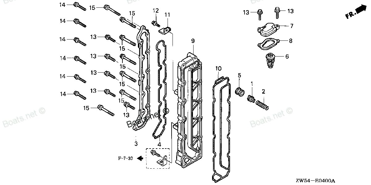
19315-ZW5-000 SEE PART DETAILS - PRI; COVER, THERMOSTAT Honda
BF115A1 LA, BF115A1 LCA, BF115A1 XA, BF115A1 XCA, BF115A2 LA, BF115A2 LCA, BF115A2 XA, BF115A2 XCA, BF115A3 LA, BF115A3 LCA, BF115A3 XA, BF115A3 XCA, BF115A4 LA, BF115A4 LCA, BF115A4 XA, BF115A4 XCA, BF115A5 LA, BF115A5 LCA, BF115A5 XA, BF115A5 XCA,
SEE

Price: query
Rating:
You can buy parts:
As an associate, we earn commssions on qualifying purchases through the links below

$40.92
17-03-2024
0.25[0.11] pounds
US: PowerToolReplacement
Honda 19315-ZW5-000 Cover Thermostat
Honda Honda 19315-ZW5-000 Cover Thermostat
Honda Honda 19315-ZW5-000 Cover Thermostat
Number on catalog scheme: 7
Compatible models:
BF115A1 LA
BF115A1 LCA
BF115A1 XA
BF115A1 XCA
BF115A2 LA
BF115A2 LCA
BF115A2 XA
BF115A2 XCA
BF115A3 LA
BF115A3 LCA
BF115A3 XA
BF115A3 XCA
BF115A4 LA
BF115A4 LCA
BF115A4 XA
BF115A4 XCA
BF115A5 LA
BF115A5 LCA
BF115A5 XA
BF115A5 XCA
BF115A6 LA
BF115A6 LCA
BF115A6 XA
BF115A6 XCA
BF115AK0 LA
BF115AK0 XA
BF115AX LA
BF115AX LCA
BF115AX XA
BF115AX XCA
BF115AY LA
BF115AY LCA
BF115AY XA
BF115AY XCA
BF130A1 LA
BF130A1 LCA
BF130A1 XA
BF130A1 XCA
BF130A2 LA
BF130A2 LCA
BF130A2 XA
BF130A2 XCA
BF130A3 LA
BF130A3 LCA
BF130A3 XA
BF130A3 XCA
BF130A4 LA
BF130A4 LCA
BF130A4 XA
BF130A4 XCA
BF130AX LA
BF130AX LCA
BF130AX XA
BF130AX XCA
BF130AY LA
BF130AY LCA
BF130AY XA
BF130AY XCA
Honda
Honda entire parts catalog list:
- THERMOSTAT » 19315-ZW5-000
- THERMOSTAT » 19315-ZW5-000
- THERMOSTAT » 19315-ZW5-000
- THERMOSTAT » 19315-ZW5-000
- THERMOSTAT » 19315-ZW5-000
- THERMOSTAT » 19315-ZW5-000
- THERMOSTAT » 19315-ZW5-000
- THERMOSTAT » 19315-ZW5-000
- THERMOSTAT » 19315-ZW5-000
- THERMOSTAT » 19315-ZW5-000
- THERMOSTAT » 19315-ZW5-000
- THERMOSTAT » 19315-ZW5-000
- THERMOSTAT » 19315-ZW5-000
- THERMOSTAT » 19315-ZW5-000
- THERMOSTAT » 19315-ZW5-000
- THERMOSTAT » 19315-ZW5-000
- THERMOSTAT » 19315-ZW5-000
- THERMOSTAT » 19315-ZW5-000
- THERMOSTAT » 19315-ZW5-000
- THERMOSTAT » 19315-ZW5-000
- THERMOSTAT » 19315-ZW5-000
- THERMOSTAT » 19315-ZW5-000
- THERMOSTAT » 19315-ZW5-000
- THERMOSTAT » 19315-ZW5-000
- THERMOSTAT » 19315-ZW5-000
- THERMOSTAT » 19315-ZW5-000
- THERMOSTAT » 19315-ZW5-000
- THERMOSTAT » 19315-ZW5-000
- THERMOSTAT » 19315-ZW5-000
- THERMOSTAT » 19315-ZW5-000
- THERMOSTAT » 19315-ZW5-000
- THERMOSTAT » 19315-ZW5-000
- THERMOSTAT » 19315-ZW5-000
- THERMOSTAT » 19315-ZW5-000
- THERMOSTAT » 19315-ZW5-000
- THERMOSTAT » 19315-ZW5-000
- THERMOSTAT » 19315-ZW5-000
- THERMOSTAT » 19315-ZW5-000
- THERMOSTAT » 19315-ZW5-000
- THERMOSTAT » 19315-ZW5-000
- THERMOSTAT » 19315-ZW5-000
- THERMOSTAT » 19315-ZW5-000
- THERMOSTAT » 19315-ZW5-000
- THERMOSTAT » 19315-ZW5-000
- THERMOSTAT » 19315-ZW5-000
- THERMOSTAT » 19315-ZW5-000
- THERMOSTAT » 19315-ZW5-000
- THERMOSTAT » 19315-ZW5-000
- THERMOSTAT » 19315-ZW5-000
- THERMOSTAT » 19315-ZW5-000
- THERMOSTAT » 19315-ZW5-000
- THERMOSTAT » 19315-ZW5-000
- THERMOSTAT » 19315-ZW5-000
- THERMOSTAT » 19315-ZW5-000
- THERMOSTAT » 19315-ZW5-000
- THERMOSTAT » 19315-ZW5-000
- THERMOSTAT » 19315-ZW5-000
- THERMOSTAT » 19315-ZW5-000
Information:
Piston, Rings And Connecting Rods
One-piece aluminum pistons are used in most applications. Engines with higher cylinder pressures require one-piece steel pistons. Refer to the Parts Manual in order to obtain information about the type of pistons that are used in a specific engine.Aluminum and Steel One-Piece Pistons
The aluminum and steel pistons have an iron band for the compression ring. This helps to reduce wear on the compression ring groove. The pistons have three rings:
Compression ring
Intermediate ring
Oil ringAll of the rings are located above the piston pin bore. The compression ring is a Keystone ring. Keystone rings have a tapered shape. The action of the ring in the piston groove that is tapered helps prevent seizure of the rings. Seizure of the rings is caused by deposits of carbon. The intermediate ring is rectangular with a sharp lower edge. The oil ring is a standard type of ring or a conventional type of ring. Oil returns to the crankcase through slots in the bottom of the groove.Oil from the piston cooling jets sprays the underside of the pistons. The spray lubricates the pistons and the spray cools the pistons. The spray also improves the pistons life and the spray also improves the rings life. The aluminum pistons use a single jet. The steel pistons use two jets. Refer to the Specifications, "Piston Cooling Jet" for more information.The connecting rod has a taper on the pin bore end. This taper gives the connecting rod and the piston more strength. The additional strength is concentrated in the areas with the most load. Two bolts hold the connecting rod cap to the connecting rod. This design keeps the connecting rod width to a minimum, so that the connecting rod can be removed through the cylinder. You must keep the rod and the original cap together.Crankshaft
The crankshaft changes the combustion forces in the cylinder into usable rotating torque which powers the machine. A vibration damper is used at the front of the crankshaft to reduce torsional vibrations (twist on the crankshaft) that can damage to the engine.The crankshaft drives a group of gears on the front of the engine. The gear group drives the following devices:
Oil pump
Camshaft
High pressure common rail fuel pump
Auxiliary water pump (If Equipped)In addition, belt pulleys on the front of the crankshaft drive the following components:
Radiator fan (If Equipped)
Water pump
Alternator (If Equipped)Hydrodynamic seals are used at both ends of the crankshaft to control oil leakage. The hydrodynamic grooves in the seal lip move lubrication oil back into the crankcase as the crankshaft turns. The front seal is located in the front housing. The rear seal is installed in the flywheel housing.
Illustration 1 g01449227
Schematic of oil passages In crankshaft
(1) Oil gallery
(2) Main bearings
(3) Connecting rod bearings Pressurized oil is supplied to all main bearings from the oil gallery (1) through drilled holes in the webs of the cylinder block. The oil then flows through drilled holes in the crankshaft in order to provide oil to the connecting rod bearings (3). The crankshaft is held in place by seven main bearings (2). A thrust bearing next to the rear main bearing controls the end play of the crankshaft.Vibration Damper
The force from combustion in the cylinders will cause the crankshaft to twist. This is called torsional vibration. If the vibration is too great, the crankshaft will be damaged. The vibration damper limits the torsional vibrations to an acceptable amount in order to prevent damage to the crankshaft.Viscous Vibration Damper
Illustration 2 g03823727
Cross section of viscous vibration damper
(4) Case
(9) Crankshaft
(10) Weight The viscous vibration damper is installed on the front of crankshaft (4). The viscous vibration damper has a weight (9) in a case (10). The space between the weight and the case is filled with a viscous fluid. The weight moves in the case in order to limit the torsional vibration.Camshaft
The camshaft is located in the upper left side of the cylinder block. The camshaft is driven by gears at the front of the engine. Seven bearings support the camshaft. A thrust plate is mounted between the camshaft drive gear and a shoulder of the camshaft in order to control the end play of the camshaft.The camshaft is driven by an idler gear which is driven by the crankshaft gear. The camshaft rotates in the same direction as the crankshaft. The crankshaft rotates in the counterclockwise direction when the engine is viewed from the flywheel end of the engine. There are timing marks on the crankshaft gear, the idler gear, and the camshaft gear in order to ensure the correct camshaft timing to the crankshaft for proper valve operation. As the camshaft turns, each lobe moves a lifter assembly. There are two lifter assemblies for each cylinder. Each lifter assembly moves a pushrod. Each pushrod moves a valve (exhaust) or a set of valves (inlet). The camshaft must be in time with the crankshaft. The relation of the camshaft lobes to the crankshaft position causes the valves in each cylinder to operate at the correct time.
Parts see Honda:
16957-ZE1-812

16957-ZE1-812 SEE PART DETAILS - PRI; GASKET, VALVE (Honda Code 3440708).
BF2.3DK2 LCHA, BF2.3DK2 SCHA, BF2AM SA, BF2AM SAB, BF2AW LA, BF2AW SA, BF2AW SAB, BF2D1 LCHA, BF2D1 SA, BF2D1 SAB, BF2D1 SCAB, BF2D1 SCHA, BF2D1 SHA, BF2D2 LCHA, BF2D2 SA, BF2D2 SAB, BF2D2 SCAB, BF2D2 SCHA, BF2D2 SHA, BF2D3 LCHA, BF2D3 SA, BF2D3 SAB,
95700-06012-00
95700-06012-00 SEE PART DETAILS - SUP; BOLT, FLANGE (6X12) (Honda Code 0487025).
BF2AM SA, BF5AM LA, BF5AM SA
94101-06800

94101-06800 SEE PART DETAILS - PRI; WASHER, PLAIN (6MM) (Honda Code 0345900).
BF2AM SA, BF2AM SAB, BF2AW LA, BF2AW SA, BF2AW SAB
90014-ZV1-010

90014-ZV1-010 SEE PART DETAILS - PRI; BOLT, FLANGE (5X22) (Honda Code 7496573).
BF15A1 LA, BF15A1 SA, BF15A2 LA, BF15A2 SA, BF15AM LA, BF15AM SA, BF15AW LA, BF15AW SA, BF15AX LA, BF15AX SA, BF15AY LA, BF15AY SA, BF25A1 LHA, BF25A1 SHA, BF25A2 LHA, BF25A2 SHA, BF25A3 LHA, BF25A3 SHA, BF25D4 LHA, BF25D4 SHA, BF25D5 LHA, BF25D5 SHA
87121-ZV1-C00

87121-ZV1-C00 SEE PART DETAILS - SUP; MARK, RR. (Honda Code 3747177).
BF5AM LA, BF5AM SA, BF5AX LA, BF5AX SA
19210-881-A01

19210-881-A01 SEE PART DETAILS - SUP; IMPELLER, PUMP (Honda Code 3739604).
BF5AM LA, BF5AM SA, BF5AX LA, BF5AX SA, BF8AM LA, BF8AM SA, BF8AM XA, BF8AX LA, BF8AX SA, BF8AX XA
90014-ZV1-000
90014-ZV1-000 SEE PART DETAILS - SUP; BOLT, FLANGE (5X22) (Honda Code 1986090).
BF15A1 LA, BF15A1 SA, BF15A2 LA, BF15A2 SA, BF15AM LA, BF15AM SA, BF15AW LA, BF15AW SA, BF15AX LA, BF15AX SA, BF15AY LA, BF15AY SA, BF25A1 LHA, BF25A1 SHA, BF25A2 LHA, BF25A2 SHA, BF25A3 LHA, BF25A3 SHA, BF25AW LHA, BF25AW SHA, BF25AX LHA, BF25AX SHA
92101-06016-0B

92101-06016-0B SEE PART DETAILS - PRI; BOLT, HEX. (6X16) (Honda Code 2801181).
BF15A1 LA, BF15A1 LAS, BF15A1 SA, BF15A1 SAS, BF15A1 XAS, BF15A2 LA, BF15A2 LAS, BF15A2 SA, BF15A2 SAS, BF15A2 XAS, BF15AM LA, BF15AM LAS, BF15AM SA, BF15AM SAS, BF15AM XAS, BF15AW LA, BF15AW LAS, BF15AW SA, BF15AW SAS, BF15AW XAS, BF15AX LA, BF15AX