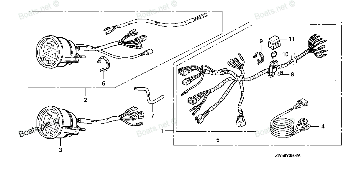
32540-ZY3-800AHR SEE PART DETAILS - PRI; HARNESS KIT, METER (DIGITAL) (Honda Code 8095200). (INCLUDE 32540-ZY3-801 Honda
BF115A4 LA, BF115A4 XA, BF115A5 LA, BF115A5 LCA, BF115A5 XA, BF115A5 XCA, BF115A6 LA, BF115A6 LCA, BF115A6 XA, BF115A6 XCA, BF115AK0 LA, BF115AK0 XA, BF130A4 LA, BF130A4 LCA, BF130A4 XA, BF130A4 XCA, BF135A4 LA, BF135A4 XA, BF135A4 XCA, BF135A5 LA, B
SEE
 (Honda Code 8095200). (INCLUDE 32540-ZY3-801 Honda parts")
Price: query
Rating:
Number on catalog scheme: 1
Compatible models:
BF115A4 LA
BF115A4 XA
BF115A5 LA
BF115A5 LCA
BF115A5 XA
BF115A5 XCA
BF115A6 LA
BF115A6 LCA
BF115A6 XA
BF115A6 XCA
BF115AK0 LA
BF115AK0 XA
BF130A4 LA
BF130A4 LCA
BF130A4 XA
BF130A4 XCA
BF135A4 LA
BF135A4 XA
BF135A4 XCA
BF135A5 LA
BF135A5 XA
BF135A5 XCA
BF135A6 LA
BF135A6 XA
BF135A6 XCA
BF135AK0 LA
BF135AK0 XA
BF135AK0 XCA
BF150A4 LA
BF150A4 XA
BF150A4 XCA
BF150A5 LA
BF150A5 XA
BF150A5 XCA
BF150A6 LA
BF150A6 XA
BF150A6 XCA
BF150AK0 LA
BF150AK0 XA
BF150AK0 XCA
BF200A4 LA
BF200A4 XA
BF200A4 XCA
BF200A4 XXA
BF200A4 XXCA
BF200A5 LA
BF200A5 XA
BF200A5 XCA
BF200A5 XXA
BF200A5 XXCA
BF200A6 LA
BF200A6 XA
BF200A6 XCA
BF200A6 XXA
BF200A6 XXCA
BF200AK0 LA
BF200AK0 XA
BF200AK0 XCA
BF225A4 LA
BF225A4 XA
BF225A4 XCA
BF225A4 XXA
BF225A4 XXCA
BF225A5 LA
BF225A5 XA
BF225A5 XCA
BF225A5 XXA
BF225A5 XXCA
BF225A6 LA
BF225A6 XA
BF225A6 XCA
BF225A6 XXA
BF225A6 XXCA
BF225AK0 LA
BF225AK0 XA
BF225AK0 XCA
BF225AK0 XXA
BF225AK0 XXCA
BF75DK0 LHTA
BF75DK0 LRTA
BF90DK0 LHTA
BF90DK0 LRTA
BF90DK0 XRTA
Honda
Honda entire parts catalog list:
- METER (DIGITAL) » 32540-ZY3-800AHR
- METER (DIGITAL) » 32540-ZY3-800AHR
- METER (DIGITAL) » 32540-ZY3-800AHR
- METER (DIGITAL) » 32540-ZY3-800AHR
- METER (DIGITAL) » 32540-ZY3-800AHR
- METER (DIGITAL) » 32540-ZY3-800AHR
- METER (DIGITAL) » 32540-ZY3-800AHR
- METER (DIGITAL) » 32540-ZY3-800AHR
- METER (DIGITAL) » 32540-ZY3-800AHR
- METER (DIGITAL) » 32540-ZY3-800AHR
- METER (DIGITAL) » 32540-ZY3-800AHR
- METER (DIGITAL) » 32540-ZY3-800AHR
- METER (DIGITAL) » 32540-ZY3-800AHR
- METER (DIGITAL) » 32540-ZY3-800AHR
- METER (DIGITAL) » 32540-ZY3-800AHR
- METER (DIGITAL) » 32540-ZY3-800AHR
- METER (3) » 32540-ZY3-800AHR
- METER (3) » 32540-ZY3-800AHR
- METER (3) » 32540-ZY3-800AHR
- METER (3) » 32540-ZY3-800AHR
- METER (3) » 32540-ZY3-800AHR
- METER (3) » 32540-ZY3-800AHR
- METER (3) » 32540-ZY3-800AHR
- METER (3) » 32540-ZY3-800AHR
- METER (3) » 32540-ZY3-800AHR
- METER (3) » 32540-ZY3-800AHR
- METER (3) » 32540-ZY3-800AHR
- METER (3) » 32540-ZY3-800AHR
- METER (3) » 32540-ZY3-800AHR
- METER (3) » 32540-ZY3-800AHR
- METER (3) » 32540-ZY3-800AHR
- METER (3) » 32540-ZY3-800AHR
- METER (3) » 32540-ZY3-800AHR
- METER (3) » 32540-ZY3-800AHR
- METER (3) » 32540-ZY3-800AHR
- METER (3) » 32540-ZY3-800AHR
- METER (3) » 32540-ZY3-800AHR
- METER (3) » 32540-ZY3-800AHR
- METER (3) » 32540-ZY3-800AHR
- METER (3) » 32540-ZY3-800AHR
- METER (2) » 32540-ZY3-800AHR
- METER (2) » 32540-ZY3-800AHR
- METER (2) » 32540-ZY3-800AHR
- METER (2) » 32540-ZY3-800AHR
- METER (2) » 32540-ZY3-800AHR
- METER (2) » 32540-ZY3-800AHR
- METER (2) » 32540-ZY3-800AHR
- METER (2) » 32540-ZY3-800AHR
- METER (2) » 32540-ZY3-800AHR
- METER (2) » 32540-ZY3-800AHR
- METER (1) » 32540-ZY3-800AHR
- METER (1) » 32540-ZY3-800AHR
- METER (1) » 32540-ZY3-800AHR
- METER (1) » 32540-ZY3-800AHR
- METER (1) » 32540-ZY3-800AHR
- METER (1) » 32540-ZY3-800AHR
- METER (1) » 32540-ZY3-800AHR
- METER (1) » 32540-ZY3-800AHR
- METER (2) » 32540-ZY3-800AHR
- METER (2) » 32540-ZY3-800AHR
- METER (2) » 32540-ZY3-800AHR
- METER (2) » 32540-ZY3-800AHR
- METER (2) » 32540-ZY3-800AHR
- METER (2) » 32540-ZY3-800AHR
- METER (2) » 32540-ZY3-800AHR
- METER (2) » 32540-ZY3-800AHR
- METER (2) » 32540-ZY3-800AHR
- METER (2) » 32540-ZY3-800AHR
- METER (1) » 32540-ZY3-800AHR
- METER (1) » 32540-ZY3-800AHR
- METER (1) » 32540-ZY3-800AHR
- METER (1) » 32540-ZY3-800AHR
- METER (1) » 32540-ZY3-800AHR
- METER (1) » 32540-ZY3-800AHR
- METER (1) » 32540-ZY3-800AHR
- METER (1) » 32540-ZY3-800AHR
- METER (1) » 32540-ZY3-800AHR
- METER (1) » 32540-ZY3-800AHR
- SPEEDOMETER KIT (DIGITAL) » 32540-ZY3-800AHR
- SPEEDOMETER KIT (DIGITAL) » 32540-ZY3-800AHR
- SPEEDOMETER KIT (DIGITAL) » 32540-ZY3-800AHR
- SPEEDOMETER KIT (DIGITAL) » 32540-ZY3-800AHR
- SPEEDOMETER KIT (DIGITAL) » 32540-ZY3-800AHR
Information:
Inspection points1. Cylinder head Using a heavy accurate straight edge and a feeler gauge, check the bottom face for warpage in three positions lengthwise, two crosswise and two widthwise as shown in the illustration. If warpage exceeds the limit, reface the bottom face with a surface grinder.
Unit: mm (in.)
Checking cylinder head bottom face for warpage2. Rocker arms and rocker shaftMeasure the bore in the rocker arm for the rocker shaft and the diameter of the rocker shaft to find the clearance between the arm and shaft. If the clearance has reached the limit, replace the rocker arm. If it exceeds the limit, replace both arm and shaft.
Unit: mm (in.)
Measuring rocker arm and rocker shaft3. Valve springs Check the squareness and free length. If the squareness and/or free length exceeds the limit, replace the spring.
Unit: mm (in.)
Testing valve spring4. Valve push rods Using V-blocks and a dial indicator, check for bend. If the bend exceeds the limit, replace the push rod.
Unit: mm (in.)
Checking bend of valve push rod5. Valves, valve guides and valve seats(1) Diameter of valve stemMeasure the diameter of the valve stem as shown in the illustration. If the stem is worn beyond the limit, or if it is abnormally worn, replace the valve.
Unit: mm (in.)
Measuring valve stem(2) Clearance between valve stem and valve guideThe valve guide wears more rapidly at its both ends than at any other parts. Measure the bore in the guide for the stem at its ends with an inside micrometer caliper to find the clearance between the stem and guide. If the clearance exceeds the limit, replace the guide or valve whichever is badly worn.
Measuring valve guide
Unit: mm (in.) Before measuring the valve guides, clear the guides of lacquer and carbon.(3) Valve guide replacement (a) Remove the guide from the cylinder head by pushing it with a tool and an arbor press from the bottom side of the head.(b) Install a new guide into the cylinder head by pushing it with an arbor press from the upper side of the head until the specified height to the top of the guide is obtained.(c) Insert a new valve into the guide and make sure the valve slides in the guide freely.(d) After the valve guide has been replaced, check the valve contact with its seat.
Height to top of valve guide(4) Valves(a) Put a small amount of Prussian blue or read lead on the valve face. Hold the valve with a valve lapping tool (commercially available) and press it against the seat to check its contact.
Checking valve contact with seat(b) The width of contact must be uniform all the way around both seat and valve. If the contact is bad, reface the valve and seat.
Valve and valve seat contact(c) If the valve margin (valve lip thickness) exceeds the limit, replace the valve.
Unit: mm (in.)
Valve margin and sinkage(d) If the valve sinkage (the dimension from the top of a closed valve to the face of cylinder head) exceeds the limit, recondition the valve seat or replace the cylinder head assembly.
Unit: mm (in.)(5) Valve refacing(a) Set the valve refacer at an angle of 45° and grind the valve.(b) The valve margin must be not less than the limit. If the margin seems to be less than the limit when the valve is refaced, replace the valve.
Refacing valve face(6) Valve seat refacing(a) Before refacing the valve seat, check the clearance between the valve and guide, and replace the guide if necessary.(b) Cut the valve seat with a valve seat cutter (commercially available), or grind it with a valve seat grinder, and finish the width of valve seat and the angle of seat face to the correct values.
Unit: mm (in.) (c) After refacing the valve seat, put lapping compound on the valve face and lap the valve in the valve seat.
Valve seat width and valve face angle(7) Valve lappingBe sure to lap the valves in the seats after refacing or replacing the valves or valve seats.(a) Put a small amount of lapping compound on the valve face. a) Do not put lapping compound on the valve stem.b) Use a lapping compound of 120 to 150 mesh for initial lapping and a compound of finer than 200 mesh for finish lapping.c) Mixing the compound with a small amount of engine oil will help put the compound on the valve face uniformly.(b) Using a lapping tool, hold the valve against the seat and rotate it only a part of a turn, then raise the valve off its seal,
Lapping valve in seatrotating it to a new position. Press the valve against the seal for another part of a turn. Repeat this operation until the compound wears and loses its cutting property.(c) Wash the valve and valve seat with dry cleaning solvent.(d) Apply engine oil to the valve and lap it in the seat.(e) Check the valve face for contact.6. Combustion jet replacement Replace the combustion jets only when they are cracked or defective.(1) To remove the jet, insert a 6 mm (0.24 in.) diameter round bar through the bore in the cylinder head for the glow plug and tap around the jet.
Removing combustion jet(2) To install a new jet, put the jet in position in the head with its tangential orifice in alignment with the center of the main chamber and tap it with a plastic hammer.
Installing combustion jetTIMING GEARS AND FLYWHEEL
Inspection points1. Camshaft(1) Clearance between journal and bushing Measure the diameter of the journal and the bore in the bushing for the shaft to find the clearance as shown in the illustration. If the clearance exceeds the limit, replace the bushing.
Unit: mm (in.)
Measuring camshaft journal
Measuring bore in camshaft bushing(2) Bushing replacementUse Camshaft Bushing Installer (ST332340) (special tool) for camshaft bushing replacement.(a) RemovalRemove the oil pan. Using a "remover" end of the Installer, push out the bushing into the cylinder block. Crush and take out the bushing from the block.
Removing camshaft bushing(b) Installation Install a new bushing in position with its oil holes in alignment with those of the oil gallery.
Installing
Parts see Honda:
87538-ZW1-740

87538-ZW1-740 SEE PART DETAILS - PRI; LABEL, CAUTION OPERATOR (Honda Code 4948014). (ENGLISH)
BF15D3 LGA, BF15D3 LHA, BF15D3 LHGA, BF15D3 LHSA, BF15D3 LHTA, BF15D3 LRA, BF15D3 LRTA, BF15D3 SHA, BF15D3 SHGA, BF15D3 SHSA, BF15D3 SHTA, BF15D3 SRTA, BF15D3 XHA, BF15D3 XHGA, BF15D4 LGA, BF15D4 LHA, BF15D4 LHGA, BF15D4 LHSA, BF15D4 LHTA, BF15D4 LRA
06411-ZW1-010
06411-ZW1-010 SEE PART DETAILS - SUP; METAL KIT, ANODE (Honda Code 8159857).
BF115A1 LA, BF115A1 LCA, BF115A1 XA, BF115A1 XCA, BF115A2 LA, BF115A2 LCA, BF115A2 XA, BF115A2 XCA, BF115A3 LA, BF115A3 LCA, BF115A3 XA, BF115A3 XCA, BF115A4 LA, BF115A4 LCA, BF115A4 XA, BF115A4 XCA, BF115A5 LA, BF115A5 LCA, BF115A5 XA, BF115A5 XCA,
06240-ZW7-U00

06240-ZW7-U00 SEE PART DETAILS - PRI; BOX KIT, R. REMOTE CONTROL (Honda Code 6796163). (FLUSH MOUNT)
BF115A1 LA, BF115A1 LCA, BF115A1 XA, BF115A1 XCA, BF115A2 LA, BF115A2 LCA, BF115A2 XA, BF115A2 XCA, BF115A3 LA, BF115A3 LCA, BF115A3 XA, BF115A3 XCA, BF115A4 LA, BF115A4 LCA, BF115A4 XA, BF115A4 XCA, BF115A5 LA, BF115A5 LCA, BF115A5 XA, BF115A5 XCA,
13400-PT3-010

13400-PT3-010 SEE PART DETAILS - PRI; SHAFT, RR. BALANCER (Honda Code 3339173).
BF115A1 LA, BF115A1 LCA, BF115A1 XA, BF115A1 XCA, BF115A2 LA, BF115A2 LCA, BF115A2 XA, BF115A2 XCA, BF115A3 LA, BF115A3 LCA, BF115A3 XA, BF115A3 XCA, BF115A4 LA, BF115A4 LCA, BF115A4 XA, BF115A4 XCA, BF115A5 LA, BF115A5 LCA, BF115A5 XA, BF115A5 XCA,
12000-ZW5-020ZA

12000-ZW5-020ZA SEE PART DETAILS - PRI; BLOCK ASSY., CYLINDER *NH8* (DARK GRAY)
BF115A1 LA, BF115A1 LCA, BF115A1 XA, BF115A1 XCA, BF115A2 LA, BF115A2 LCA, BF115A2 XA, BF115A2 XCA, BF115A3 LA, BF115A3 LCA, BF115A3 XA, BF115A3 XCA, BF115A4 LA, BF115A4 LCA, BF115A4 XA, BF115A4 XCA, BF115A5 LA, BF115A5 LCA, BF115A5 XA, BF115A5 XCA,
90006-ZW5-010
90006-ZW5-010 SEE PART DETAILS - PRI; BOLT 2, STUD (10X32) (Honda Code 7207335).
BF115A1 LA, BF115A1 LCA, BF115A1 XA, BF115A1 XCA, BF115A2 LA, BF115A2 LCA, BF115A2 XA, BF115A2 XCA, BF115A3 LA, BF115A3 LCA, BF115A3 XA, BF115A3 XCA, BF115A4 LA, BF115A4 LCA, BF115A4 XA, BF115A4 XCA, BF115A5 LA, BF115A5 LCA, BF115A5 XA, BF115A5 XCA,
41161-ZW5-010
41161-ZW5-010 SEE PART DETAILS - PRI; SHAFT, PROPELLER (Honda Code 7094600).
BF115A1 LA, BF115A1 XA, BF115A2 LA, BF115A2 XA, BF115A3 LA, BF115A3 XA, BF115A4 LA, BF115A4 XA, BF115A5 LA, BF115A5 XA, BF115A6 LA, BF115A6 XA, BF115AK0 LA, BF115AK0 XA, BF115AX LA, BF115AX XA, BF115AY LA, BF115AY XA, BF130A1 LA, BF130A1 XA, BF130A2
16900-ZV5-902
16900-ZV5-902 SEE PART DETAILS - PRI; JOINT ASSY., FUEL
BF115A2 LA, BF115A2 LCA, BF115A2 XA, BF115A2 XCA, BF115A3 LA, BF115A3 XA, BF115A4 LA, BF115A4 LCA, BF115A4 XA, BF115A4 XCA, BF115A5 LA, BF115A5 LCA, BF115A5 XA, BF115A5 XCA, BF115A6 LA, BF115A6 LCA, BF115A6 XA, BF115A6 XCA, BF115AK0 LA, BF115AK0 XA,