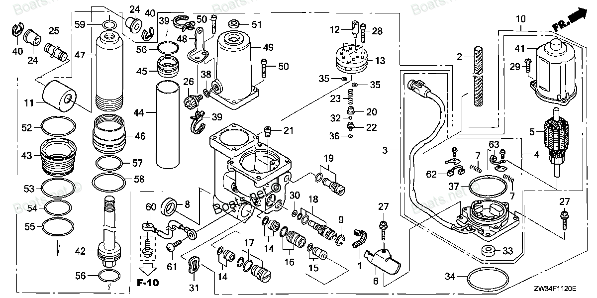
56000-ZW4-H13 SEE PART DETAILS - SUP; TRIM-TILT ASSY., POWER (Honda Code 8566770). Honda
BF40A4 LHTA, BF40A4 LRTA, BF40A5 LHTA, BF40A5 LRTA, BF40A6 LHTA, BF40A6 LRTA, BF40AK0 LRTA, BF50A4 LHTA, BF50A4 LRTA, BF50A4 SRJA, BF50A4 XRTA, BF50A5 LHTA, BF50A5 LRTA, BF50A5 SRJA, BF50A5 XRTA, BF50A6 LHTA, BF50A6 LRTA, BF50A6 SRJA, BF50A6 XRTA, BF
SEE
. Honda parts")
Price: query
Rating:
Number on catalog scheme: 10
Compatible models:
Honda entire parts catalog list:
- POWER TRIM-TILT » 56000-ZW4-H13
- POWER TRIM-TILT » 56000-ZW4-H13
- POWER TRIM-TILT » 56000-ZW4-H13
- POWER TRIM-TILT » 56000-ZW4-H13
- POWER TRIM-TILT » 56000-ZW4-H13
- POWER TRIM-TILT » 56000-ZW4-H13
- POWER TRIM-TILT » 56000-ZW4-H13
- POWER TRIM-TILT » 56000-ZW4-H13
- POWER TRIM-TILT » 56000-ZW4-H13
- POWER TRIM-TILT » 56000-ZW4-H13
- POWER TRIM-TILT » 56000-ZW4-H13
- POWER TRIM-TILT » 56000-ZW4-H13
- POWER TRIM-TILT » 56000-ZW4-H13
- POWER TRIM-TILT » 56000-ZW4-H13
- POWER TRIM-TILT » 56000-ZW4-H13
- POWER TRIM-TILT » 56000-ZW4-H13
- POWER TRIM-TILT » 56000-ZW4-H13
- POWER TRIM-TILT » 56000-ZW4-H13
- POWER TRIM-TILT » 56000-ZW4-H13
- POWER TRIM-TILT » 56000-ZW4-H13
- POWER TRIM-TILT » 56000-ZW4-H13
- POWER TRIM-TILT » 56000-ZW4-H13
Information:
1. Remove bolts (2) from bracket on cylinder head.2. Remove bolt (1) from turbocharger.3. Remove air inlet pipe and air cleaner bracket as a unit. 4. Remove oil supply line (4) for turbocharger.5. Disconnect oil return line for turbocharger.6. Remove bolts (5) from turbocharger and remove turbocharger.7. Remove coupling (3) from exhaust elbow.Install Turbocharger
1. Install coupling (1) in exhaust elbow.2. Put 9M3710 Anti-Seize Compound on threads of turbocharger bolts.3. Put the turbocharger (2) in position on exhaust manifold and install bolts. Tighten bolts to a torque of 40 4 lb.ft. (5.5 0.6 mkg).4. Install supply line and connect return line for turbocharger.5. Install air inlet pipe and air cleaner bracket as a unit.end by: a) install air cleaner housingDisassemble Turbocharger
start by: a) remove turbocharger 1. Put the turbocharger in position on tool (A).2. Put a mark on the compressor cover and housings for installation purpose.3. Remove "V" clamp (2) and remove compressor cover (1). 4. Remove "V" clamp (3) and remove shaft housing from turbine housing (4). 5. Put shaft housing in tool (B). Remove nut and compressor wheel (5) from the shaft.
When loosening the nut, do not put a side force on the shaft.
6. Remove shaft housing from tool (B) and remove turbine wheel (7) and shaft from housing.7. Remove seal ring (6) from the turbine wheel. 8. Remove snap ring and insert (8) from the housing. 9. Push the sleeve (9) out of the insert. Remove the two seal rings from the sleeve. 10. Remove deflector (10), ring (15), sleeve (11), bearing (12), ring (16), snap ring (13), bearing (17) and snap ring (14) from the housing. Remove snap rings (13) and (14) with tool (C). Check the oil hole in bearing (12). If the oil hole is not open this will cause a bearing failure. 11. Turn the housing around and remove snap ring (18) and shroud (22).12. Remove snap ring (19), sleeve (20), bearing (21), and snap ring (23). Remove the two snap rings with tool (C).13. Inspect all parts and install new parts as needed.Assemble Turbocharger
1. Make sure all oil passages are open and clean. Put clean engine oil on all parts before assembly. 2. Install snap ring (4), bearing (3), sleeve (2) and snap ring (1). Install the two snap rings with tool (A). Install the snap rings with the round side toward the bearing. 3. Install shroud (5) on the housing. Turn the shroud to make sure it is down on the housing even. The high part (web) (6) on shroud, will keep the shroud from turning on the housing after assembly.4. Install snap ring that holds the shroud in place.5. Install the bearing and two snap rings in the compressor end of the housing. Install the snap rings with tool (A). Install the snap rings with the round side toward the bearing. 6. Install seal ring (7) on the shaft. Install turbine wheel (8) and shaft in the housing.7. Put housing in position on tool (B). 8. Install ring (13), bearing (11), sleeve (12), ring (10) and deflector (9) in the housing.
The oil hole in bearing (11) must be open and clean.
9. Install the seal rings on sleeve (15). Install sleeve in insert (14). 10. Install insert in the housing and install snap ring (17).11. Install compressor wheel (16) on shaft. 12. Put clean engine oil on the threads of the shaft. Install the nut (18) and tighten to a torque of 15 1 lb.ft. (2.1 0.14 mkg).
When tightening nut do not put a side force on the shaft.
13. Install shaft housing into the turbine housing. Install "V" clamp (21) and tighten clamp to a torque of 120 lb.in. (138.4 cm.kg).14. Install compressor cover (19) and "V" clamp (20). Tighten "V" clamp to a torque of 120 lb.ft. (138.4 cm.kg).end by: a) install turbocharger
Parts see Honda:
94301-08140

94301-08140 SEE PART DETAILS - PRI; PIN A, DOWEL (8X14) (Honda Code 0069310).
BF115A1 LA, BF115A1 LCA, BF115A1 XA, BF115A1 XCA, BF115A2 LA, BF115A2 LCA, BF115A2 XA, BF115A2 XCA, BF115A3 LA, BF115A3 LCA, BF115A3 XA, BF115A3 XCA, BF115A4 LA, BF115A4 LCA, BF115A4 XA, BF115A4 XCA, BF115A5 LA, BF115A5 LCA, BF115A5 XA, BF115A5 XCA,
19315-ZV5-010ZA
19315-ZV5-010ZA SEE PART DETAILS - SUP; COVER, THERMOSTAT *NH8* (Honda Code 4646154). (DARK GRAY)
BF25A1 LHA, BF25A1 LHSA, BF25A1 LRSA, BF25A1 SHA, BF25A1 SHSA, BF25A1 SRSA, BF25A1 XRSA, BF25A2 LHA, BF25A2 LHSA, BF25A2 LRSA, BF25A2 SHA, BF25A2 SHSA, BF25A2 SRSA, BF25A2 XRSA, BF25A3 LHA, BF25A3 LHSA, BF25A3 LRSA, BF25A3 SHA, BF25A3 SHSA, BF25A3 SR
14520-ZV5-020

14520-ZV5-020 SEE PART DETAILS - PRI; SPRING, TIMING BELT ADJUSTING (Honda Code 6979454).
BF35AM LHA, BF35AM LRA, BF35AM LRTA, BF35AM SHA, BF35AM XRTA, BF40A1 LHA, BF40A1 LHTA, BF40A1 LRA, BF40A1 LRTA, BF40A1 XRTA, BF40A2 LHA, BF40A2 LHTA, BF40A2 LRA, BF40A2 LRTA, BF40A2 XRTA, BF40A3 LHA, BF40A3 LHTA, BF40A3 LRA, BF40A3 LRTA, BF40A3 XRTA,
15400-PFB-007

15400-PFB-007 SEE PART DETAILS - PRI; FILTER, OIL (Honda Code 7219611).
BF25A1 LHA, BF25A1 LHSA, BF25A1 LRSA, BF25A1 SHA, BF25A1 SHSA, BF25A1 SRSA, BF25A1 XRSA, BF25A2 LHA, BF25A2 LHSA, BF25A2 LRSA, BF25A2 SHA, BF25A2 SHSA, BF25A2 SRSA, BF25A2 XRSA, BF25A3 LHA, BF25A3 LHSA, BF25A3 LRSA, BF25A3 SHA, BF25A3 SHSA, BF25A3 SR
24813-ZW5-U01
24813-ZW5-U01 SEE PART DETAILS - PRI; GRIP, REMOTE CONTROL HANDLE (Honda Code 6799555).
BF115A1 LA, BF115A1 LCA, BF115A1 XA, BF115A1 XCA, BF115A2 LA, BF115A2 LCA, BF115A2 XA, BF115A2 XCA, BF115A3 LA, BF115A3 LCA, BF115A3 XA, BF115A3 XCA, BF115A4 LA, BF115A4 LCA, BF115A4 XA, BF115A4 XCA, BF115A5 LA, BF115A5 LCA, BF115A5 XA, BF115A5 XCA,
06410-ZW4-305
06410-ZW4-305 SEE PART DETAILS - PRI; SHAFT ASSY., PROPELLER (Honda Code 8870297).
BF40A1 LHA, BF40A1 LHTA, BF40A1 LRA, BF40A1 LRTA, BF40A1 XRTA, BF40A2 LHA, BF40A2 LHTA, BF40A2 LRA, BF40A2 LRTA, BF40A2 XRTA, BF40A3 LHA, BF40A3 LHTA, BF40A3 LRA, BF40A3 LRTA, BF40A3 XRTA, BF40A4 LHA, BF40A4 LHTA, BF40A4 LRTA, BF40AY LHA, BF40AY LHTA
17650-ZW9-023

17650-ZW9-023 SEE PART DETAILS - PRI; CONNECTOR ASSY., FUEL (A)
BF115A1 LA, BF115A1 LCA, BF115A1 XA, BF115A1 XCA, BF115A2 LA, BF115A2 LCA, BF115A2 XA, BF115A2 XCA, BF115A3 LA, BF115A3 LCA, BF115A3 XA, BF115A3 XCA, BF115A4 LA, BF115A4 LCA, BF115A4 XA, BF115A4 XCA, BF115A5 LA, BF115A5 LCA, BF115A5 XA, BF115A5 XCA,
30400-ZW4-H03
30400-ZW4-H03 SEE PART DETAILS - PRI; MODULE, IGNITION CONTROL (CDI) (Honda Code 8588410).
BF40A4 LHA, BF40A4 LHTA, BF40A4 LRTA, BF40A5 LHA, BF40A5 LHTA, BF40A5 LRTA, BF40A6 LHA, BF40A6 LHTA, BF40A6 LRTA, BF40AK0 LHA, BF40AK0 LRTA, BF50A4 LHTA, BF50A4 LRTA, BF50A4 SRJA, BF50A4 XRTA, BF50A5 LHTA, BF50A5 LRTA, BF50A5 SRJA, BF50A5 XRTA, BF50A