90435-ZV5-010 SEE PART DETAILS - PRI; WASHER (10X28X5) (Honda Code 7226707). Honda
BF40A1 LHA, BF40A1 LHTA, BF40A1 LRA, BF40A1 LRTA, BF40A1 XRTA, BF40A2 LHA, BF40A2 LHTA, BF40A2 LRA, BF40A2 LRTA, BF40A2 XRTA, BF40A3 LHA, BF40A3 LHTA, BF40A3 LRA, BF40A3 LRTA, BF40A3 XRTA, BF40A4 LHA, BF40A4 LHTA, BF40A4 LRTA, BF40A5 LHA, BF40A5 LHTA
SEE
 (Honda Code 7226707). Honda parts")
Price: query
Rating:
Number on catalog scheme: 15
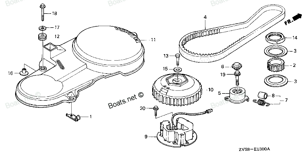
Compatible models:
BF40A1 LHA
BF40A1 LHTA
BF40A1 LRA
BF40A1 LRTA
BF40A1 XRTA
BF40A2 LHA
BF40A2 LHTA
BF40A2 LRA
BF40A2 LRTA
BF40A2 XRTA
BF40A3 LHA
BF40A3 LHTA
BF40A3 LRA
BF40A3 LRTA
BF40A3 XRTA
BF40A4 LHA
BF40A4 LHTA
BF40A4 LRTA
BF40A5 LHA
BF40A5 LHTA
BF40A5 LRTA
BF40A6 LHA
BF40A6 LHTA
BF40A6 LRTA
BF40AK0 LHA
BF40AK0 LRTA
BF40AY LHA
BF40AY LHTA
BF40AY LRA
BF40AY LRTA
BF40AY XRTA
BF40DK2 LHA
BF40DK2 LRTA
BF50A1 LHTA
BF50A1 LRA
BF50A1 LRTA
BF50A1 SRJA
BF50A1 XRTA
BF50A2 LHTA
BF50A2 LRA
BF50A2 LRTA
BF50A2 SRJA
BF50A2 XRTA
BF50A3 LHTA
BF50A3 LRA
BF50A3 LRTA
BF50A3 SRJA
BF50A3 XRTA
BF50A4 LHTA
BF50A4 LRTA
BF50A4 SRJA
BF50A4 XRTA
BF50A5 LHTA
BF50A5 LRTA
BF50A5 SRJA
BF50A5 XRTA
BF50A6 LHTA
BF50A6 LRTA
BF50A6 SRJA
BF50A6 XRTA
BF50AK0 LRTA
BF50AK0 SRJA
BF50AK0 XRTA
BF50AY LHTA
BF50AY LRA
BF50AY LRTA
BF50AY SRJA
BF50AY XRTA
BF50DK2 LRTA
BF50DK2 XRTA
BF75A1 LHTA
BF75A1 LRTA
BF75A1 XRTA
BF75A2 LHTA
BF75A2 LRTA
BF75A2 XRTA
BF75A3 LHTA
BF75A3 LRTA
BF75A3 XRTA
BF75A4 LHTA
BF75A4 LRTA
BF75A4 XRTA
BF75A5 LHTA
BF75A5 LRTA
BF75A5 XRTA
BF75A6 LHTA
BF75A6 LRTA
BF75A6 XRTA
BF90A1 JHTA
BF90A1 JRTA
BF90A1 LHTA
BF90A1 LRTA
BF90A1 XRTA
BF90A2 JHTA
BF90A2 JRTA
BF90A2 LHTA
BF90A2 LRTA
BF90A2 XRTA
BF90A3 JHTA
BF90A3 JRTA
BF90A3 LHTA
BF90A3 LRTA
BF90A3 XRTA
BF90A4 JHTA
BF90A4 JRTA
BF90A4 LHTA
BF90A4 LRTA
BF90A4 XRTA
BF90A5 JHTA
BF90A5 JRTA
BF90A5 LHTA
BF90A5 LRTA
BF90A5 XRTA
BF90A6 JHTA
BF90A6 JRTA
BF90A6 LHTA
BF90A6 LRTA
BF90A6 XRTA
Honda
Honda entire parts catalog list:
- TIMING BELT » 90435-ZV5-010
- TIMING BELT » 90435-ZV5-010
- TIMING BELT » 90435-ZV5-010
- TIMING BELT » 90435-ZV5-010
- TIMING BELT » 90435-ZV5-010
- TIMING BELT » 90435-ZV5-010
- TIMING BELT » 90435-ZV5-010
- TIMING BELT » 90435-ZV5-010
- TIMING BELT » 90435-ZV5-010
- TIMING BELT » 90435-ZV5-010
- TIMING BELT » 90435-ZV5-010
- TIMING BELT » 90435-ZV5-010
- TIMING BELT » 90435-ZV5-010
- TIMING BELT » 90435-ZV5-010
- TIMING BELT » 90435-ZV5-010
- TIMING BELT » 90435-ZV5-010
- TIMING BELT » 90435-ZV5-010
- TIMING BELT » 90435-ZV5-010
- TIMING BELT » 90435-ZV5-010
- TIMING BELT » 90435-ZV5-010
- TIMING BELT » 90435-ZV5-010
- TIMING BELT » 90435-ZV5-010
- TIMING BELT » 90435-ZV5-010
- TIMING BELT » 90435-ZV5-010
- TIMING BELT » 90435-ZV5-010
- TIMING BELT » 90435-ZV5-010
- TIMING BELT » 90435-ZV5-010
- TIMING BELT » 90435-ZV5-010
- TIMING BELT » 90435-ZV5-010
- TIMING BELT » 90435-ZV5-010
- TIMING BELT » 90435-ZV5-010
- TIMING BELT » 90435-ZV5-010
- TIMING BELT » 90435-ZV5-010
- TIMING BELT » 90435-ZV5-010
- TIMING BELT » 90435-ZV5-010
- TIMING BELT » 90435-ZV5-010
- TIMING BELT » 90435-ZV5-010
- TIMING BELT » 90435-ZV5-010
- TIMING BELT » 90435-ZV5-010
- TIMING BELT » 90435-ZV5-010
- TIMING BELT » 90435-ZV5-010
- TIMING BELT » 90435-ZV5-010
- TIMING BELT » 90435-ZV5-010
- TIMING BELT » 90435-ZV5-010
- TIMING BELT » 90435-ZV5-010
- TIMING BELT » 90435-ZV5-010
- TIMING BELT » 90435-ZV5-010
- TIMING BELT » 90435-ZV5-010
- TIMING BELT » 90435-ZV5-010
- TIMING BELT » 90435-ZV5-010
- TIMING BELT » 90435-ZV5-010
- TIMING BELT » 90435-ZV5-010
- TIMING BELT » 90435-ZV5-010
- TIMING BELT » 90435-ZV5-010
- TIMING BELT » 90435-ZV5-010
- TIMING BELT » 90435-ZV5-010
- TIMING BELT » 90435-ZV5-010
- TIMING BELT » 90435-ZV5-010
- TIMING BELT » 90435-ZV5-010
- TIMING BELT » 90435-ZV5-010
- TIMING BELT » 90435-ZV5-010
- TIMING BELT » 90435-ZV5-010
- TIMING BELT » 90435-ZV5-010
- TIMING BELT » 90435-ZV5-010
- TIMING BELT » 90435-ZV5-010
- TIMING BELT » 90435-ZV5-010
- TIMING BELT » 90435-ZV5-010
- TIMING BELT » 90435-ZV5-010
- TIMING BELT » 90435-ZV5-010
- TIMING BELT » 90435-ZV5-010
- TIMING BELT » 90435-ZV5-010
- TIMING BELT » 90435-ZV5-010
- TIMING BELT » 90435-ZV5-010
- TIMING BELT » 90435-ZV5-010
- TIMING BELT » 90435-ZV5-010
- TIMING BELT » 90435-ZV5-010
- TIMING BELT » 90435-ZV5-010
- TIMING BELT » 90435-ZV5-010
- TIMING BELT » 90435-ZV5-010
- TIMING BELT » 90435-ZV5-010
- TIMING BELT » 90435-ZV5-010
- TIMING BELT » 90435-ZV5-010
- TIMING BELT » 90435-ZV5-010
- TIMING BELT » 90435-ZV5-010
- TIMING BELT » 90435-ZV5-010
- TIMING BELT » 90435-ZV5-010
- TIMING BELT » 90435-ZV5-010
- TIMING BELT » 90435-ZV5-010
- TIMING BELT » 90435-ZV5-010
- TIMING BELT » 90435-ZV5-010
- TIMING BELT » 90435-ZV5-010
- TIMING BELT » 90435-ZV5-010
- TIMING BELT » 90435-ZV5-010
- TIMING BELT » 90435-ZV5-010
- TIMING BELT » 90435-ZV5-010
- TIMING BELT » 90435-ZV5-010
- TIMING BELT » 90435-ZV5-010
- TIMING BELT » 90435-ZV5-010
- TIMING BELT » 90435-ZV5-010
- TIMING BELT » 90435-ZV5-010
- TIMING BELT » 90435-ZV5-010
- TIMING BELT » 90435-ZV5-010
- TIMING BELT » 90435-ZV5-010
- TIMING BELT » 90435-ZV5-010
- TIMING BELT » 90435-ZV5-010
- TIMING BELT » 90435-ZV5-010
- TIMING BELT » 90435-ZV5-010
- TIMING BELT » 90435-ZV5-010
- TIMING BELT » 90435-ZV5-010
- TIMING BELT » 90435-ZV5-010
- TIMING BELT » 90435-ZV5-010
- TIMING BELT » 90435-ZV5-010
- TIMING BELT » 90435-ZV5-010
- TIMING BELT » 90435-ZV5-010
- TIMING BELT » 90435-ZV5-010
Information:
Probable Causes
Connectors and wiring
Throttle signal
Fuel injectors
Fuel system
Inlet air restriction
Exhaust systemRecommended Actions
Note: If the problem only occurs under certain conditions, test the engine under those conditions. Examples of certain conditions are high engine speed, full load, and engine operating temperature. Troubleshooting the symptoms under other conditions can give misleading results.
Table 1
Troubleshooting Test Steps Values Results
1. Inspect the Electrical Connectors and the Wiring
A. Turn the main disconnect switch to the OFF position.
B. Check for the correct installation of the ECM J1/P1 and the J2/P2 connectors. Refer to Troubleshooting, "Electrical Power Supply - Test" for additional information.
C. Check for correct installation of the following connectors:
- Connectors for the wiring harness under the valve cover
- Connectors for the engine speed/timing sensors
D. Check the power and ground connections to the ECM. Refer to Troubleshooting, "Electrical Power Supply - Test" for additional information.
Connectors and Wiring
Result: The connectors and wiring appear to be OK.
Proceed to Test Step 2.
Result: There is a problem with the connectors and/or wiring.
Repair: Repair or replace the connectors or wiring. Ensure that all of the seals are properly in place and ensure that the connectors are coupled.
If the problem is not resolved, proceed to Test Step 2.
2. Check for an Intermittent Throttle Signal
A. Connect Caterpillar® Electronic Technician (Cat ET) to the service tool connector.
B. Use Cat ET to monitor the following:
- "Throttle Position"
C. Verify that the status for "Throttle Position" is stable and that the engine is able to reach high idle speed.
Throttle Signal
Result: The status for "Throttle Position" is stable.
Proceed to Test Step 3.
Result: The status for "Throttle Position" is not stable.
Repair: Repair or replace damaged components. Refer to Troubleshooting, "Speed Control - Test" for additional information.
If the problem is not resolved, proceed to Test Step 3.
3. Test the Fuel Injectors
A. Connect Cat ET.
B. Use Cat ET to perform the following fuel injector tests:
- "Injector Solenoid Test"
- "Cylinder Cutout Test"
Refer to Troubleshooting, "Cat ET Service Features" for additional information.
Fuel Injectors
Result: The tests were successful.
Proceed to Test Step 4.
Result: The tests were not successful.
Repair: Diagnose the problem. Repair or replace damaged components.
If the problem is not resolved, proceed to Test Step 4.
4. Inspect the Fuel System
Refer to Testing and Adjusting, "Fuel System Inspection" for additional information.
A. Visually check the fuel level in the fuel tank. Do not rely on the fuel gauge only.
B. Ensure that the vent in the fuel cap is not filled with debris.
C. Ensure that the fuel supply valve (if equipped) is in the full OPEN position.
Note: Cold weather adversely affects the characteristics of the fuel. Refer to the engines Operation and Maintenance Manual for information on improving the characteristics of the fuel during cold-weather operation.
D. Check fuel quality. Refer to Testing and Adjusting, "Fuel Quality - Test" for additional information. Check the fuel tank for debris or foreign objects which may block the fuel supply.
E. Check for fuel leaks.
Fuel System
Result: The fuel system is OK.
Proceed to Test Step 5.
Result: The fuel system is NOT OK.
Repair: Repair or replace damaged fuel system components.
If the problem is not resolved, proceed to Test Step 5.
5. Check for a Restriction in the Inlet Air System
A. Check the air filter restriction indicator, if equipped. Refer to the Operation and Maintenance Manual for additional information.
B. Measure the inlet air restriction for each turbocharger. Refer to Troubleshooting, "Inlet Air Is Restricted" for additional information.
Restriction
Result: The inlet air restriction is OK.
Proceed to Test Step 6.
Result: The inlet air restriction is NOT OK. An imbalance in the system is discovered.
Repair: Repair or replace damaged inlet air system components. Equalize the inlet air restriction for each of the turbochargers.
If the problem is not resolved, proceed to Test Step 6.
6. Check for a Restriction in the Exhaust System
Note: A restriction of the exhaust can cause high cylinder temperatures.
The Engine Control Module (ECM) may monitor the following parameters in order to calculate an exhaust temperature:
- Barometric pressure
- Intake manifold air temperature
- Engine speed
Certain operating conditions may cause the calculated exhaust temperature to increase to a level that may damage engine components. If a high exhaust temperature occurs, the ECM derates the engine in order to reduce the calculated exhaust temperature. The engine is derated only to a level that allows the calculated exhaust temperature to return to an acceptable level.
A. Measure the exhaust restriction during engine operation with a load. For data that is specific to your engine, refer to the Technical Marketing Information (TMI).
Restrictions
Result: The exhaust restriction measurement is NOT OK.
Repair: Repair or replace damaged exhaust system components.
Verify that the repair eliminated the problem.
If the procedure did not correct the issue, contact your Cat dealer Technical Communicator (TC). For further assistance, your TC can confer with the Dealer Solutions Network (DSN).
Parts see Honda:
94301-08140

94301-08140 SEE PART DETAILS - PRI; PIN A, DOWEL (8X14) (Honda Code 0069310).
BF115A1 LA, BF115A1 LCA, BF115A1 XA, BF115A1 XCA, BF115A2 LA, BF115A2 LCA, BF115A2 XA, BF115A2 XCA, BF115A3 LA, BF115A3 LCA, BF115A3 XA, BF115A3 XCA, BF115A4 LA, BF115A4 LCA, BF115A4 XA, BF115A4 XCA, BF115A5 LA, BF115A5 LCA, BF115A5 XA, BF115A5 XCA,
17661-921-000
17661-921-000 SEE PART DETAILS - SUP; PRIMER BULB (Honda Code 0444083).
BF115A1 LA, BF115A1 LCA, BF115A1 XA, BF115A1 XCA, BF115A2 LA, BF115A2 LCA, BF115A2 XA, BF115A2 XCA, BF115A3 LA, BF115A3 LCA, BF115A3 XA, BF115A3 XCA, BF115A4 LA, BF115A4 LCA, BF115A4 XA, BF115A4 XCA, BF115AX LA, BF115AX LCA, BF115AX XA, BF115AX XCA,
92101-06020-4J
92101-06020-4J SEE PART DETAILS - PRI; BOLT, HEX. (6X20) (Honda Code 2801207).
BF115A1 LA, BF115A1 LCA, BF115A1 XA, BF115A1 XCA, BF115A2 LA, BF115A2 LCA, BF115A2 XA, BF115A2 XCA, BF115A3 LA, BF115A3 LCA, BF115A3 XA, BF115A3 XCA, BF115A4 LA, BF115A4 LCA, BF115A4 XA, BF115A4 XCA, BF115A5 LA, BF115A5 LCA, BF115A5 XA, BF115A5 XCA,
31630-ZV5-912

31630-ZV5-912 SEE PART DETAILS - PRI; COIL ASSY., CHARGE (12V/10A) (Honda Code 6957054).
BF35AM LHA, BF35AM LRA, BF35AM LRTA, BF35AM SHA, BF35AM XRTA, BF40A1 LHA, BF40A1 LHTA, BF40A1 LRA, BF40A1 LRTA, BF40A1 XRTA, BF40A2 LHA, BF40A2 LHTA, BF40A2 LRA, BF40A2 LRTA, BF40A2 XRTA, BF40A3 LHA, BF40A3 LHTA, BF40A3 LRA, BF40A3 LRTA, BF40A3 XRTA,
17929-ZV3-010
17929-ZV3-010 SEE PART DETAILS - PRI; BRACKET, THROTTLE CABLE (Honda Code 7855299).
BF35AM LHA, BF35AM SHA, BF40A1 LHA, BF40A1 LHTA, BF40A2 LHA, BF40A2 LHTA, BF40A3 LHA, BF40A3 LHTA, BF40AW LHA, BF40AW LHTA, BF40AX LHA, BF40AX LHTA, BF40AY LHA, BF40AY LHTA, BF45AM LHA, BF50A1 LHTA, BF50A2 LHTA, BF50A3 LHTA, BF50AW LHTA, BF50AX LHTA,
35370-ZV5-823

35370-ZV5-823 SEE PART DETAILS - PRI; SWITCH ASSY., POWER TRIM-TILT (Honda Code 7161383).
BF115A1 LA, BF115A1 LCA, BF115A1 XA, BF115A1 XCA, BF115A2 LA, BF115A2 LCA, BF115A2 XA, BF115A2 XCA, BF115A3 LA, BF115A3 LCA, BF115A3 XA, BF115A3 XCA, BF115A4 LA, BF115A4 LCA, BF115A4 XA, BF115A4 XCA, BF115A5 LA, BF115A5 LCA, BF115A5 XA, BF115A5 XCA,
16101-ZW4-D21
16101-ZW4-D21 SEE PART DETAILS - SUP; CARBURETOR ASSY. (#1,#2) (Honda Code 5686837).
BF50AW LHTA, BF50AW LRA, BF50AW LRTA, BF50AW SRJA, BF50AW XRTA, BF50AX LHTA, BF50AX LRA, BF50AX LRTA, BF50AX SRJA, BF50AX XRTA, BF50AY LHTA, BF50AY LRA, BF50AY LRTA, BF50AY SRJA, BF50AY XRTA
90120-ZV4-010
90120-ZV4-010 SEE PART DETAILS - PRI; BOLT, HEX. (6X40)
BF115A1 LA, BF115A1 LCA, BF115A1 XA, BF115A1 XCA, BF115A2 LA, BF115A2 LCA, BF115A2 XA, BF115A2 XCA, BF115A3 LA, BF115A3 LCA, BF115A3 XA, BF115A3 XCA, BF115A4 LA, BF115A4 LCA, BF115A4 XA, BF115A4 XCA, BF115A5 LA, BF115A5 LCA, BF115A5 XA, BF115A5 XCA,