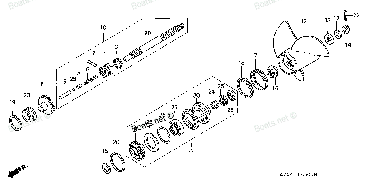
90548-ZV5-010 SEE PART DETAILS - PRI; WASHER, PLAIN (54MM) (Honda Code 7226723). Honda
BF35AM LHA, BF35AM LRA, BF35AM LRTA, BF35AM SHA, BF35AM XRTA, BF40A1 LHA, BF40A1 LHTA, BF40A1 LRA, BF40A1 LRTA, BF40A1 XRTA, BF40A2 LHA, BF40A2 LHTA, BF40A2 LRA, BF40A2 LRTA, BF40A2 XRTA, BF40A3 LHA, BF40A3 LHTA, BF40A3 LRA, BF40A3 LRTA, BF40A3 XRTA,
SEE
 (Honda Code 7226723). Honda parts")
Price: query
Rating:
Number on catalog scheme: 21
Compatible models:
BF35AM LHA
BF35AM LRA
BF35AM LRTA
BF35AM SHA
BF35AM XRTA
BF40A1 LHA
BF40A1 LHTA
BF40A1 LRA
BF40A1 LRTA
BF40A1 XRTA
BF40A2 LHA
BF40A2 LHTA
BF40A2 LRA
BF40A2 LRTA
BF40A2 XRTA
BF40A3 LHA
BF40A3 LHTA
BF40A3 LRA
BF40A3 LRTA
BF40A3 XRTA
BF40A4 LHA
BF40A4 LHTA
BF40A4 LRTA
BF40A5 LHA
BF40A5 LHTA
BF40A5 LRTA
BF40A6 LHA
BF40A6 LHTA
BF40A6 LRTA
BF40AK0 LHA
BF40AK0 LRTA
BF40AW LHA
BF40AW LHTA
BF40AW LRA
BF40AW LRTA
BF40AW XRTA
BF40AX LHA
BF40AX LHTA
BF40AX LRA
BF40AX LRTA
BF40AX XRTA
BF40AY LHA
BF40AY LHTA
BF40AY LRA
BF40AY LRTA
BF40AY XRTA
BF45AM LHA
BF45AM LRA
BF45AM LRTA
BF45AM SRTA
BF45AM XRTA
BF50A1 LHTA
BF50A1 LRA
BF50A1 LRTA
BF50A1 XRTA
BF50A2 LHTA
BF50A2 LRA
BF50A2 LRTA
BF50A2 XRTA
BF50A3 LHTA
BF50A3 LRA
BF50A3 LRTA
BF50A3 XRTA
BF50A4 LHTA
BF50A4 LRTA
BF50A4 XRTA
BF50A5 LHTA
BF50A5 LRTA
BF50A5 XRTA
BF50A6 LHTA
BF50A6 LRTA
BF50A6 XRTA
BF50AK0 LRTA
BF50AK0 XRTA
BF50AW LHTA
BF50AW LRA
BF50AW LRTA
BF50AW XRTA
BF50AX LHTA
BF50AX LRA
BF50AX LRTA
BF50AX XRTA
BF50AY LHTA
BF50AY LRA
BF50AY LRTA
BF50AY XRTA
Honda
Honda entire parts catalog list:
- PROPELLER » 90548-ZV5-010
- PROPELLER » 90548-ZV5-010
- PROPELLER » 90548-ZV5-010
- PROPELLER » 90548-ZV5-010
- PROPELLER » 90548-ZV5-010
- PROPELLER » 90548-ZV5-010
- PROPELLER » 90548-ZV5-010
- PROPELLER » 90548-ZV5-010
- PROPELLER » 90548-ZV5-010
- PROPELLER » 90548-ZV5-010
- PROPELLER » 90548-ZV5-010
- PROPELLER » 90548-ZV5-010
- PROPELLER » 90548-ZV5-010
- PROPELLER » 90548-ZV5-010
- PROPELLER » 90548-ZV5-010
- PROPELLER » 90548-ZV5-010
- PROPELLER » 90548-ZV5-010
- PROPELLER » 90548-ZV5-010
- PROPELLER » 90548-ZV5-010
- PROPELLER » 90548-ZV5-010
- PROPELLER PROPELLER SHAFT » 90548-ZV5-010
- PROPELLER PROPELLER SHAFT » 90548-ZV5-010
- PROPELLER PROPELLER SHAFT » 90548-ZV5-010
- PROPELLER PROPELLER SHAFT » 90548-ZV5-010
- PROPELLER PROPELLER SHAFT » 90548-ZV5-010
- PROPELLER PROPELLER SHAFT » 90548-ZV5-010
- PROPELLER PROPELLER SHAFT » 90548-ZV5-010
- PROPELLER PROPELLER SHAFT » 90548-ZV5-010
- PROPELLER PROPELLER SHAFT » 90548-ZV5-010
- PROPELLER PROPELLER SHAFT » 90548-ZV5-010
- PROPELLER PROPELLER SHAFT » 90548-ZV5-010
- PROPELLER » 90548-ZV5-010
- PROPELLER » 90548-ZV5-010
- PROPELLER » 90548-ZV5-010
- PROPELLER » 90548-ZV5-010
- PROPELLER » 90548-ZV5-010
- PROPELLER » 90548-ZV5-010
- PROPELLER » 90548-ZV5-010
- PROPELLER » 90548-ZV5-010
- PROPELLER » 90548-ZV5-010
- PROPELLER » 90548-ZV5-010
- PROPELLER » 90548-ZV5-010
- PROPELLER » 90548-ZV5-010
- PROPELLER » 90548-ZV5-010
- PROPELLER » 90548-ZV5-010
- PROPELLER » 90548-ZV5-010
- PROPELLER » 90548-ZV5-010
- PROPELLER » 90548-ZV5-010
- PROPELLER » 90548-ZV5-010
- PROPELLER » 90548-ZV5-010
- PROPELLER » 90548-ZV5-010
- PROPELLER » 90548-ZV5-010
- PROPELLER » 90548-ZV5-010
- PROPELLER » 90548-ZV5-010
- PROPELLER » 90548-ZV5-010
- PROPELLER » 90548-ZV5-010
- PROPELLER » 90548-ZV5-010
- PROPELLER » 90548-ZV5-010
- PROPELLER » 90548-ZV5-010
- PROPELLER » 90548-ZV5-010
- PROPELLER » 90548-ZV5-010
- PROPELLER » 90548-ZV5-010
- PROPELLER » 90548-ZV5-010
- PROPELLER PROPELLER SHAFT » 90548-ZV5-010
- PROPELLER PROPELLER SHAFT » 90548-ZV5-010
- PROPELLER PROPELLER SHAFT » 90548-ZV5-010
- PROPELLER PROPELLER SHAFT » 90548-ZV5-010
- PROPELLER PROPELLER SHAFT » 90548-ZV5-010
- PROPELLER PROPELLER SHAFT » 90548-ZV5-010
- PROPELLER PROPELLER SHAFT » 90548-ZV5-010
- PROPELLER PROPELLER SHAFT » 90548-ZV5-010
- PROPELLER PROPELLER SHAFT » 90548-ZV5-010
- PROPELLER PROPELLER SHAFT » 90548-ZV5-010
- PROPELLER PROPELLER SHAFT » 90548-ZV5-010
- PROPELLER » 90548-ZV5-010
- PROPELLER » 90548-ZV5-010
- PROPELLER » 90548-ZV5-010
- PROPELLER » 90548-ZV5-010
- PROPELLER » 90548-ZV5-010
- PROPELLER » 90548-ZV5-010
- PROPELLER » 90548-ZV5-010
- PROPELLER » 90548-ZV5-010
- PROPELLER » 90548-ZV5-010
- PROPELLER » 90548-ZV5-010
- PROPELLER » 90548-ZV5-010
- PROPELLER » 90548-ZV5-010
Information:
Recommended Actions
Note: The procedures have been listed in order of probability. Complete the procedures in order.
Table 1
Troubleshooting Test Steps Values Results
1. Active Codes and Logged Codes
A. Establish communication between Caterpillar Electronic Technician (ET) and the Electronic Control Module (ECM). Refer to Troubleshooting, "Electronic Service Tools", if necessary.
B. Download the "Product Status Report" from the engine ECM before performing any troubleshooting or clearing diagnostic trouble codes.
Troubleshoot any active codes before continuing with this procedure.
Codes
Result: There are active codes.
Troubleshoot any active codes before continuing with this procedure.
Result: There are no active codes.
Proceed to Test Step 2.
2. Restriction in the Air Inlet and Exhaust System
A. Check the air filter restriction indicator, if equipped. Clean plugged air filters or replace plugged air filters. Refer to the Operation and Maintenance Manual.
B. Check the air inlet and exhaust system for restrictions and/or leaks.
Restrictions
Result: There are restrictions in the air inlet or exhaust system.
Make the necessary repairs, Verify that the repair eliminated the problem.
Result: There are no restrictions in the air inlet or exhaust system.
Proceed to Test Step 4.
3. Check the Fuel System
Refer to Systems Operation/Testing and Adjusting, "Fuel System" for additional information.
A. Visually check the fuel level in the fuel tank. Do not rely on the fuel gauge only.
B. Ensure that the vent in the fuel cap is not filled with debris.
C. Inspect the fuel system for external leaks.
D. Check that there are no external leaks, no air in the clear primary fuel filter. Change the primary fuel filter and the in-line filter for the fuel transfer pump.
E.Check fuel quality. Refer to Systems Operation/Testing and Adjusting, Fuel Quality - Test, for the proper procedure. Check the fuel tank for debris or foreign objects which may block the fuel supply.
F. Check for the proper operation of the fuel transfer pump. Replace the pre-filter if excessive contamination or if the maintenance interval is exceeded. Refer to Systems Operation/Testing and Adjusting, Fuel System, for test information.
Fuel system
Result: The fuel system is OK.
Proceed to Test Step 6.
Result: The fuel system is not OK.
Replace the fuel filters. Clean the primary filter/water separator of debris. Refer to the Operation and Maintenance Manual for details.
4. Proper Operation of the Turbocharger
A. Check for proper operation of the turbocharger.
Turbocharger
Result: The turbocharger is operating properly.
Proceed to Test Step 5.
Result: The turbocharger is not operating properly.
Repair or replace the turbocharger. Verify that the repair eliminated the problem.
5. Fuel Injectors
A. If service has been performed on the engine fuel system recently, verify that the injector trim codes in the Engine ECM match the injector for each cylinder. If injectors were moved between cylinders or if an injector was replaced and the injector trim codes were not updated in the Engine ECM, this can cause an engine miss.
B. Access the "Cylinder Cutout Test" in the "Diagnostic Tests" under the "Diagnostics" menu. Cut out each cylinder one at a time to listen for improvements in the engine. If engine sound improves while cutting out a specific cylinder or cylinders, then check that the injector(s) are working properly by using 440-6907 Injector Kit .
Note: The injector deliver quantity is not a reliable indicator of a failed injector. It is not recommended to use that test in determining if an injector is failed.
Fuel Injectors
Result: If injector(s) trim codes for each cylinder do not match what is in the Engine ECM, then refer to Special Instruction, REHS9707, for the procedure to install the new injector QR codes within the Engine ECM and on-line. Confirm that this resolves the issue.
Result: If injector(s) are found to be defective, then replace the injector(s). Refer to Disassembly and Assembly, Electronic Unit Injector - Remove and Install. Refer to Special Instruction, REHS9707, for the procedure to install the new injector QR codes within the Engine ECM and online. Confirm that this resolves the issue.
Note: If two or more injectors are not working properly, this is likely a result of water in the fuel, bad fuel, or contaminated fuel. Contaminated fuel can occur by pre-filling the fuel filter or contamination during a previous repair of the fuel system. The root cause needs to be determined to prevent a repeat occurrence.
Result: There are no previous known services on fuel system and there was no noticeable improvement during the cylinder cut out test. The customer could have ordered injectors through parts and did not change the injector trim codes in the Engine ECM. Visually confirm that the injector trim code for each cylinder matches what is in the Engine ECM. Refer to Special Instruction, REHS9707, for the procedure to install the new injector QR codes within the Engine ECM and on-line.
6. Machine Hydraulics Causing Excessive Load
Refer to the machine System Operation/Testing and Adjustmanual to ensure that machine hydraulics are working properly.
Machine Hydraulics
Result: Machine hydraulics are causing an excessive load.
Make the necessary repairs.
Parts see Honda:
17661-921-000

17661-921-000 SEE PART DETAILS - SUP; PRIMER BULB (Honda Code 0444083).
BF115A1 LA, BF115A1 LCA, BF115A1 XA, BF115A1 XCA, BF115A2 LA, BF115A2 LCA, BF115A2 XA, BF115A2 XCA, BF115A3 LA, BF115A3 LCA, BF115A3 XA, BF115A3 XCA, BF115A4 LA, BF115A4 LCA, BF115A4 XA, BF115A4 XCA, BF115AX LA, BF115AX LCA, BF115AX XA, BF115AX XCA,
17700-ZV5-010

17700-ZV5-010 SEE PART DETAILS - SUP; TUBE ASSY., FUEL (Honda Code 4729000).
BF15AM LA, BF15AM LAS, BF15AM SA, BF15AM SAS, BF15AM XAS, BF15AW LA, BF15AW LAS, BF15AW SA, BF15AW SAS, BF15AW XAS, BF25A1 LHA, BF25A1 LHSA, BF25A1 LRSA, BF25A1 SHA, BF25A1 SHSA, BF25A1 SRSA, BF25A1 XRSA, BF25AW LHA, BF25AW LHSA, BF25AW LRSA, BF25AW
15400-PFB-004

15400-PFB-004 SEE PART DETAILS - PRI; FILTER, OIL (TOYO ROKI) (Honda Code 6341531).
BF15D3 LGA, BF15D3 LHA, BF15D3 LHGA, BF15D3 LHSA, BF15D3 LHTA, BF15D3 LRA, BF15D3 LRTA, BF15D3 SHA, BF15D3 SHGA, BF15D3 SHSA, BF15D3 SHTA, BF15D3 SRTA, BF15D3 XHA, BF15D3 XHGA, BF15D4 LGA, BF15D4 LHA, BF15D4 LHGA, BF15D4 LHSA, BF15D4 LHTA, BF15D4 LRA
23162-ZV5-024
23162-ZV5-024 SEE PART DETAILS - PRI; GASKET, PRIMARY GEAR CASE (Honda Code 6725303).
BF35AM LHA, BF35AM LRA, BF35AM LRTA, BF35AM SHA, BF35AM XRTA, BF40A1 LHA, BF40A1 LHTA, BF40A1 LRA, BF40A1 LRTA, BF40A1 XRTA, BF40A2 LHA, BF40A2 LHTA, BF40A2 LRA, BF40A2 LRTA, BF40A2 XRTA, BF40A3 LHA, BF40A3 LHTA, BF40A3 LRA, BF40A3 LRTA, BF40A3 XRTA,
50381-ZV5-000

50381-ZV5-000 SEE PART DETAILS - SUP; SHAFT, TILTING (Honda Code 3704954).
BF15D3 LGA, BF15D3 LHA, BF15D3 LHGA, BF15D3 LHSA, BF15D3 LHTA, BF15D3 LRA, BF15D3 LRTA, BF15D3 SHGA, BF15D3 SHTA, BF15D3 SRTA, BF15D3 XHA, BF15D3 XHGA, BF15D4 LRTA, BF15D4 SRTA, BF20D3 LGA, BF20D3 LHA, BF20D3 LHGA, BF20D3 LHSA, BF20D3 LHTA, BF20D3 LR
35180-ZV7-013
35180-ZV7-013 SEE PART DETAILS - SUP; SWITCH ASSY., EMERGENCY STOP (Honda Code 5291653).
BF115A1 LA, BF115A1 LCA, BF115A1 XA, BF115A1 XCA, BF115A2 LA, BF115A2 LCA, BF115A2 XA, BF115A2 XCA, BF115A3 LA, BF115A3 LCA, BF115A3 XA, BF115A3 XCA, BF115A4 LA, BF115A4 LCA, BF115A4 XA, BF115A4 XCA, BF115A5 LA, BF115A5 LCA, BF115A5 XA, BF115A5 XCA,
06240-ZW5-U40

06240-ZW5-U40 SEE PART DETAILS - PRI; BOX KIT, R. REMOTE CONTROL (Honda Code 6796122). (TOP MOUNT SINGL
BF115A1 LA, BF115A1 LCA, BF115A1 XA, BF115A1 XCA, BF115A2 LA, BF115A2 LCA, BF115A2 XA, BF115A2 XCA, BF115A3 LA, BF115A3 LCA, BF115A3 XA, BF115A3 XCA, BF115A4 LA, BF115A4 LCA, BF115A4 XA, BF115A4 XCA, BF115A5 LA, BF115A5 LCA, BF115A5 XA, BF115A5 XCA,
14400-ZV5-004
14400-ZV5-004 SEE PART DETAILS - SUP; BELT, TIMING
BF40A1 LHA, BF40A1 LHTA, BF40A1 LRA, BF40A1 LRTA, BF40A1 XRTA, BF40A2 LHA, BF40A2 LHTA, BF40A2 LRA, BF40A2 LRTA, BF40A2 XRTA, BF40A3 LHA, BF40A3 LHTA, BF40A3 LRA, BF40A3 LRTA, BF40A3 XRTA, BF40AY LHA, BF40AY LHTA, BF40AY LRA, BF40AY LRTA, BF40AY XRTA