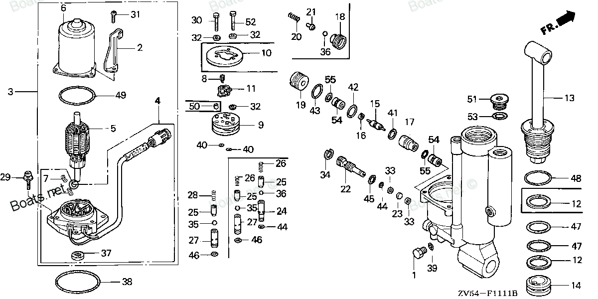
90604-ZV5-821 SEE PART DETAILS - SUP; CIRCLIP (INNER) (Honda Code 4594750). Honda
BF35AM LRTA, BF35AM XRTA, BF40AW LHTA, BF40AW LRTA, BF40AW XRTA, BF45AM LRTA, BF45AM SRTA, BF45AM XRTA, BF50AW LHTA, BF50AW LRTA, BF50AW XRTA
SEE
 (Honda Code 4594750). Honda parts")
Price: query
Rating:
Number on catalog scheme: 34
Compatible models:
Honda entire parts catalog list:
- POWER TILT COMPONENTS » 90604-ZV5-821
- POWER TILT COMPONENTS » 90604-ZV5-821
- POWER TILT COMPONENTS » 90604-ZV5-821
- POWER TILT COMPONENTS » 90604-ZV5-821
- POWER TILT COMPONENTS » 90604-ZV5-821
- POWER TILT COMPONENTS » 90604-ZV5-821
- POWER TILT COMPONENTS » 90604-ZV5-821
- POWER TILT COMPONENTS » 90604-ZV5-821
- POWER TILT COMPONENTS » 90604-ZV5-821
- POWER TILT COMPONENTS » 90604-ZV5-821
- POWER TILT COMPONENTS » 90604-ZV5-821
Information:
Table 1
Required Tools
Tool Part Number Part Description Qty
A 370-4653 Counterweight Tool 1
B 4C-5597 Anti-Seize Compound 1
Keep all parts clean from contaminants.Contaminants may cause rapid wear and shortened component life.
Illustration 1 g03461476
Ensure that turbocharger (3) is clean and free from damage. Inspect the turbocharger for wear. Refer to System Operation, Testing and Adjusting, "Turbocharger Inspect" for more information. If any part of the turbocharger is worn or damaged, the complete turbocharger must be replaced.
Test wastegate actuator (25) for correct operation. Refer to System Operation, Testing and Adjusting, "Turbocharger Inspect" for more information. If any part of the wastegate actuator is worn or damaged, the complete turbocharger must be replaced.
Illustration 2 g03461477
Clean the gasket surface of exhaust manifold (21). If necessary, install studs (24) to turbocharger (3). Tighten the studs to a torque of 18 N m (160 lb in).
Install a new gasket (23) to studs (24).
Position turbocharger (3) onto the exhaust manifold and install nuts (22) finger tight. The nuts (22) should not constrain the turbocharger and prevent Tooling (A) from correctly positioning the turbocharger onto the exhaust manifold.
Use Tooling (A) to align turbocharger (3). Note: Ensure that the turbocharger is correctly oriented.
Illustration 3 g03459359
Turbocharger tightening sequence viewed from the exhaust manifold.
Tighten nuts (22) in the sequence shown in Illustration 3 to a torque of 44 N m (32 lb ft).
Remove Tooling (A) from turbocharger (3).
Illustration 4 g03461478
Illustration 5 g03461479
Remove plugs and caps from tube assemblies. Ensure that tube assembly (20) and tube assembly (16) are clean and free from damage. Replace any damaged components.
Position a new gasket (18) (not shown) onto tube assembly (20).
Install bolts (19) to tube assembly (20). Tighten the bolt to a torque of 22 N m (195 lb in).
Remove the plug from oil inlet port (26). Lubricate the turbocharger bearings with clean engine oil through the oil inlet port. Rotate the wheel of the compressor several times in order to lubricate the bearings.
Install a new sealing washer (17) to banjo bolt (15). Install the banjo bolt to tube assembly (16). Install the remaining new sealing washer (17) to banjo bolt (15).
Position tube assembly (16) onto turbocharger (3). Tighten the banjo bolt to a torque of 20 N m (177 lb in).
Illustration 6 g03461480
Use Tooling (B) to lubricate the allen head bolt for V-band clamp (4). Position V-band clamp (4) onto air duct (14).
Position hose assembly (10) and air duct (14) onto the outlet of turbocharger (3) and the turbocharger. Ensure that V-band clamp (4) is correctly seated on the air duct (14) and turbocharger (3).
Tighten the allen head bolt for V-band clamp (4) to a torque of 12 N m (106 lb in).
Tighten hose clamps (9) to a torque of 6 N m (53 lb in).
Use Tooling (B) to lubricate the allen head bolt for V-band clamp (8). Position V-band clamp (8) onto the turbocharger.
Use Tooling (B) to lubricate the allen head bolt for V-band clamp (2). Position V-band clamp (2) onto elbow (1).
Position elbow (1) onto the turbocharger and turbocharger (3).
Tighten allen head bolt for V-band clamp (2) and allen head bolt for V-band clamp (8) finger tight. Ensure that the V-band clamps are seated correctly onto the turbochargers.
Tighten allen head bolt for V-band clamp (2) and allen head bolt for V-band clamp (8) to a torque of 12 N m (106 lb in).
Connect hose assembly (6) (not shown) to the wastegate actuator. Slide clip (3) along the hose assembly ensure that the clip is correctly positioned.
Connect hose assembly (14) to turbocharger (3). Slide clip (13) along the hose assembly ensure that the clip is correctly positioned.
Install bolt (7) (not shown) to the clip for the tube assembly. Tighten the bolt to a torque of 22 N m (195 lb in).
Connect hose assembly to air outlet (11) to turbocharger (3). Tighten the hose clamps securely.
Parts see Honda:
17661-921-010

17661-921-010 SEE PART DETAILS - PRI; PRIMER BULB (Honda Code 7604903).
BF115A1 LA, BF115A1 LCA, BF115A1 XA, BF115A1 XCA, BF115A2 LA, BF115A2 LCA, BF115A2 XA, BF115A2 XCA, BF115A3 LA, BF115A3 LCA, BF115A3 XA, BF115A3 XCA, BF115A4 LA, BF115A4 LCA, BF115A4 XA, BF115A4 XCA, BF115A5 LA, BF115A5 LCA, BF115A5 XA, BF115A5 XCA,
17700-ZV5-010

17700-ZV5-010 SEE PART DETAILS - SUP; TUBE ASSY., FUEL (Honda Code 4729000).
BF15AM LA, BF15AM LAS, BF15AM SA, BF15AM SAS, BF15AM XAS, BF15AW LA, BF15AW LAS, BF15AW SA, BF15AW SAS, BF15AW XAS, BF25A1 LHA, BF25A1 LHSA, BF25A1 LRSA, BF25A1 SHA, BF25A1 SHSA, BF25A1 SRSA, BF25A1 XRSA, BF25AW LHA, BF25AW LHSA, BF25AW LRSA, BF25AW
15400-PFB-004

15400-PFB-004 SEE PART DETAILS - PRI; FILTER, OIL (TOYO ROKI) (Honda Code 6341531).
BF15D3 LGA, BF15D3 LHA, BF15D3 LHGA, BF15D3 LHSA, BF15D3 LHTA, BF15D3 LRA, BF15D3 LRTA, BF15D3 SHA, BF15D3 SHGA, BF15D3 SHSA, BF15D3 SHTA, BF15D3 SRTA, BF15D3 XHA, BF15D3 XHGA, BF15D4 LGA, BF15D4 LHA, BF15D4 LHGA, BF15D4 LHSA, BF15D4 LHTA, BF15D4 LRA
19300-ZV5-043

19300-ZV5-043 SEE PART DETAILS - PRI; THERMOSTAT ASSY. (Honda Code 5592167). (72 DEGREES C)
BF115A1 LA, BF115A1 LCA, BF115A1 XA, BF115A1 XCA, BF115A2 LA, BF115A2 LCA, BF115A2 XA, BF115A2 XCA, BF115AX LA, BF115AX LCA, BF115AX XA, BF115AX XCA, BF115AY LA, BF115AY LCA, BF115AY XA, BF115AY XCA, BF130A1 LA, BF130A1 LCA, BF130A1 XA, BF130A1 XCA,
16700-ZV5-003
16700-ZV5-003 SEE PART DETAILS - SUP; PUMP ASSY., FUEL (Honda Code 5020466).
BF25A1 LHA, BF25A1 LHSA, BF25A1 LRSA, BF25A1 SHA, BF25A1 SHSA, BF25A1 SRSA, BF25A1 XRSA, BF25A2 LHA, BF25A2 LHSA, BF25A2 LRSA, BF25A2 SHA, BF25A2 SHSA, BF25A2 SRSA, BF25A2 XRSA, BF25AW LHA, BF25AW LHSA, BF25AW LRSA, BF25AW SHA, BF25AW SHSA, BF25AW SR
31100-ZV5-680ZA

31100-ZV5-680ZA SEE PART DETAILS - SUP; FLYWHEEL *TBLACK* (Honda Code 4367215). (BLACK)
BF35AM LHA, BF35AM LRA, BF35AM LRTA, BF35AM SHA, BF35AM XRTA, BF40A1 LHA, BF40A1 LHTA, BF40A1 LRA, BF40A1 LRTA, BF40A1 XRTA, BF40A2 LHA, BF40A2 LHTA, BF40A2 LRA, BF40A2 LRTA, BF40A2 XRTA, BF40A3 LHA, BF40A3 LHTA, BF40A3 LRA, BF40A3 LRTA, BF40A3 XRTA,
15236-ZV5-010
15236-ZV5-010 SEE PART DETAILS - PRI; BOLT, SEALING (14MM) (Honda Code 7219603).
BF25A1 LHA, BF25A1 LHSA, BF25A1 LRSA, BF25A1 SHA, BF25A1 SHSA, BF25A1 SRSA, BF25A1 XRSA, BF25A2 LHA, BF25A2 LHSA, BF25A2 LRSA, BF25A2 SHA, BF25A2 SHSA, BF25A2 SRSA, BF25A2 XRSA, BF25A3 LHA, BF25A3 LHSA, BF25A3 LRSA, BF25A3 SHA, BF25A3 SHSA, BF25A3 SR
41200-ZV5-030
41200-ZV5-030 SEE PART DETAILS - PRI; HOLDER ASSY., PROPELLER SHAFT (Honda Code 8757213).
BF35AM LHA, BF35AM LRA, BF35AM LRTA, BF35AM SHA, BF35AM XRTA, BF40A1 LHA, BF40A1 LHTA, BF40A1 LRA, BF40A1 LRTA, BF40A1 XRTA, BF40A2 LHA, BF40A2 LHTA, BF40A2 LRA, BF40A2 LRTA, BF40A2 XRTA, BF40A3 LHA, BF40A3 LHTA, BF40A3 LRA, BF40A3 LRTA, BF40A3 XRTA,