24101-ZV5-000 SHIFTER, CLUTCH (Honda Code 3702776). Honda
BF35AM LHA, BF35AM LRA, BF35AM LRTA, BF35AM SHA, BF35AM XRTA, BF40A1 LHA, BF40A1 LHTA, BF40A1 LRA, BF40A1 LRTA, BF40A1 XRTA, BF40A2 LHA, BF40A2 LHTA, BF40A2 LRA, BF40A2 LRTA, BF40A2 XRTA, BF40A3 LHA, BF40A3 LHTA, BF40A3 LRA, BF40A3 LRTA, BF40A3 XRTA,
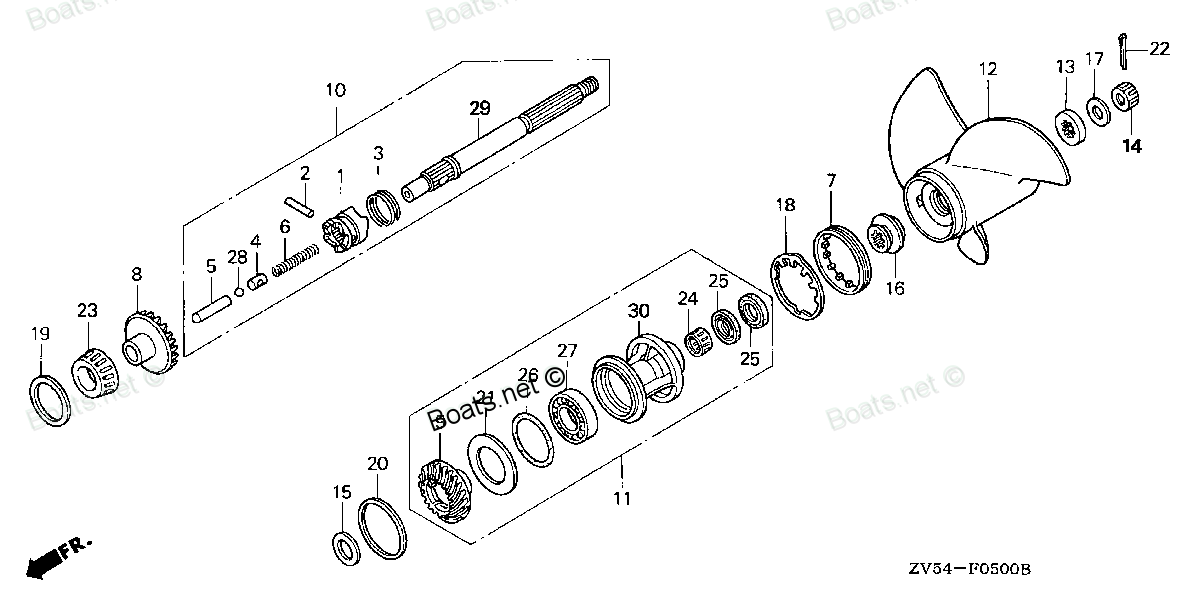
SHIFTER
. Honda parts")
Price: query
Rating:
Number on catalog scheme: 1
Compatible models:
BF35AM LHA
BF35AM LRA
BF35AM LRTA
BF35AM SHA
BF35AM XRTA
BF40A1 LHA
BF40A1 LHTA
BF40A1 LRA
BF40A1 LRTA
BF40A1 XRTA
BF40A2 LHA
BF40A2 LHTA
BF40A2 LRA
BF40A2 LRTA
BF40A2 XRTA
BF40A3 LHA
BF40A3 LHTA
BF40A3 LRA
BF40A3 LRTA
BF40A3 XRTA
BF40A4 LHA
BF40A4 LHTA
BF40A4 LRTA
BF40AW LHA
BF40AW LHTA
BF40AW LRA
BF40AW LRTA
BF40AW XRTA
BF40AX LHA
BF40AX LHTA
BF40AX LRA
BF40AX LRTA
BF40AX XRTA
BF40AY LHA
BF40AY LHTA
BF40AY LRA
BF40AY LRTA
BF40AY XRTA
BF45AM LHA
BF45AM LRA
BF45AM LRTA
BF45AM SRTA
BF45AM XRTA
BF50A1 LHTA
BF50A1 LRA
BF50A1 LRTA
BF50A1 XRTA
BF50A2 LHTA
BF50A2 LRA
BF50A2 LRTA
BF50A2 XRTA
BF50A3 LHTA
BF50A3 LRA
BF50A3 LRTA
BF50A3 XRTA
BF50A4 LHTA
BF50A4 LRTA
BF50A4 XRTA
BF50A5 LHTA
BF50A5 LRTA
BF50A5 XRTA
BF50AK0 LRTA
BF50AW LHTA
BF50AW LRA
BF50AW LRTA
BF50AW XRTA
BF50AX LHTA
BF50AX LRA
BF50AX LRTA
BF50AX XRTA
BF50AY LHTA
BF50AY LRA
BF50AY LRTA
BF50AY XRTA
Honda
Honda entire parts catalog list:
- PROPELLER » 24101-ZV5-000
- PROPELLER » 24101-ZV5-000
- PROPELLER » 24101-ZV5-000
- PROPELLER » 24101-ZV5-000
- PROPELLER » 24101-ZV5-000
- PROPELLER » 24101-ZV5-000
- PROPELLER » 24101-ZV5-000
- PROPELLER » 24101-ZV5-000
- PROPELLER » 24101-ZV5-000
- PROPELLER » 24101-ZV5-000
- PROPELLER » 24101-ZV5-000
- PROPELLER » 24101-ZV5-000
- PROPELLER » 24101-ZV5-000
- PROPELLER » 24101-ZV5-000
- PROPELLER » 24101-ZV5-000
- PROPELLER » 24101-ZV5-000
- PROPELLER » 24101-ZV5-000
- PROPELLER » 24101-ZV5-000
- PROPELLER » 24101-ZV5-000
- PROPELLER » 24101-ZV5-000
- PROPELLER PROPELLER SHAFT » 24101-ZV5-000
- PROPELLER PROPELLER SHAFT » 24101-ZV5-000
- PROPELLER PROPELLER SHAFT » 24101-ZV5-000
- PROPELLER » 24101-ZV5-000
- PROPELLER » 24101-ZV5-000
- PROPELLER » 24101-ZV5-000
- PROPELLER » 24101-ZV5-000
- PROPELLER » 24101-ZV5-000
- PROPELLER » 24101-ZV5-000
- PROPELLER » 24101-ZV5-000
- PROPELLER » 24101-ZV5-000
- PROPELLER » 24101-ZV5-000
- PROPELLER » 24101-ZV5-000
- PROPELLER » 24101-ZV5-000
- PROPELLER » 24101-ZV5-000
- PROPELLER » 24101-ZV5-000
- PROPELLER » 24101-ZV5-000
- PROPELLER » 24101-ZV5-000
- PROPELLER » 24101-ZV5-000
- PROPELLER » 24101-ZV5-000
- PROPELLER » 24101-ZV5-000
- PROPELLER » 24101-ZV5-000
- PROPELLER » 24101-ZV5-000
- PROPELLER » 24101-ZV5-000
- PROPELLER » 24101-ZV5-000
- PROPELLER » 24101-ZV5-000
- PROPELLER » 24101-ZV5-000
- PROPELLER » 24101-ZV5-000
- PROPELLER » 24101-ZV5-000
- PROPELLER » 24101-ZV5-000
- PROPELLER » 24101-ZV5-000
- PROPELLER » 24101-ZV5-000
- PROPELLER » 24101-ZV5-000
- PROPELLER » 24101-ZV5-000
- PROPELLER » 24101-ZV5-000
- PROPELLER PROPELLER SHAFT » 24101-ZV5-000
- PROPELLER PROPELLER SHAFT » 24101-ZV5-000
- PROPELLER PROPELLER SHAFT » 24101-ZV5-000
- PROPELLER PROPELLER SHAFT » 24101-ZV5-000
- PROPELLER PROPELLER SHAFT » 24101-ZV5-000
- PROPELLER PROPELLER SHAFT » 24101-ZV5-000
- PROPELLER PROPELLER SHAFT » 24101-ZV5-000
- PROPELLER » 24101-ZV5-000
- PROPELLER » 24101-ZV5-000
- PROPELLER » 24101-ZV5-000
- PROPELLER » 24101-ZV5-000
- PROPELLER » 24101-ZV5-000
- PROPELLER » 24101-ZV5-000
- PROPELLER » 24101-ZV5-000
- PROPELLER » 24101-ZV5-000
- PROPELLER » 24101-ZV5-000
- PROPELLER » 24101-ZV5-000
- PROPELLER » 24101-ZV5-000
- PROPELLER » 24101-ZV5-000
Information:
Sulfuric Acid Burn Hazard may cause serious personal injury or death.The exhaust gas cooler may contain a small amount of sulfuric acid. The use of fuel with sulfur levels greater than 15 ppm may increase the amount of sulfuric acid formed. The sulfuric acid may spill from the cooler during service of the engine. The sulfuric acid will burn the eyes, skin and clothing on contact. Always wear the appropriate personal protective equipment (PPE) that is noted on a material safety data sheet (MSDS) for sulfuric acid. Always follow the directions for first aid that are noted on a material safety data sheet (MSDS) for sulfuric acid.
Keep all parts clean from contaminants.Contaminants may cause rapid wear and shortened component life.
Note: Plug or cap all open ports with new plugs or caps.
If necessary, remove the diesel particulate mounting bracket. Refer to Disassembly and Assembly, "Support and Mounting (CEM) - Remove and Install" for the correct procedure.
Illustration 1 g02912798
Illustration 2 g02898616
Illustration 3 g02898617
If necessary, remove bolts (1) and heat shield (2) from exhaust gas recirculation (EGR) valve (4).
Slide the locking tab into the unlocked position and disconnect harness assembly (3) from EGR valve (4).
Loosen clamp (6) and position the clamp away from EGR valve (4).
Disconnect hose assembly (5) from EGR valve (4).
Remove bolt (18) from the bracket for tube assembly (19).
Remove bolt (20) and tube assembly (19) from EGR valve (4).
Remove O-ring seal (21) (not shown).
If necessary, slide hose clamp (17) along hose (16). Disconnect tube (19) from hose (16).
Apply releasing fluid prior to and during the removal of bolts (12) and bolts (14).
Remove bolts (12) and remove bolts (14). Remove flexible tube assembly (13) from the exhaust manifold.
Remove bolts (11) from EGR valve (4). Note: Note the position of different length bolts.
Remove from EGR valve (4) from the induction manifold.
If necessary, remove bolt (9) and remove tube assembly (7) from EGR valve (4). Remove O-ring seal (8) (not shown). Installation Procedure
Sulfuric Acid Burn Hazard may cause serious personal injury or death.The exhaust gas cooler may contain a small amount of sulfuric acid. The use of fuel with sulfur levels greater than 15 ppm may increase the amount of sulfuric acid formed. The sulfuric acid may spill from the cooler during service of the engine. The sulfuric acid will burn the eyes, skin and clothing on contact. Always wear the appropriate personal protective equipment (PPE) that is noted on a material safety data sheet (MSDS) for sulfuric acid. Always follow the directions for first aid that are noted on a material safety data sheet (MSDS) for sulfuric acid.
Ensure that wiring harness are correctly routed and the cable straps are not over tightened. Over tightening of the cable straps will damage the wiring harness convoluting.
Keep all parts clean from contaminants.Contaminants may cause rapid wear and shortened component life.
Ensure that all components are clean and free from wear and damage. If necessary, replace any components that are worn or damaged.
Illustration 4 g02898617
Illustration 5 g02898616
If necessary, install new O-ring seal (8) (not shown) to EGR valve (4). Install tube assembly (7) to EGR valve (4).
Install new clamp (6) to EGR valve (4).
Position a new clamp (6) onto EGR valve (4).
Install bolts (11) to EGR valve (4) finger tight.
Position clamp (6). Tighten the clamp to a torque of 10 N m (89 lb in).
Tighten bolts (11) to a torque of 25 N m (221 lb in). Note: Ensure that the bolts are installed into the correct position.
If necessary, install tube (19) to hose (16). Slide hose clamp (17) into position and tighten securely.
Install new O-ring seals (21) (not shown) to tube assembly (19).
Install tube assembly (19) to EGR valve (4).
Install bolt (18) and bolt (20) finger tight. Tighten the bolt
Tighten bolt (20) to a torque of 10 N m (89 lb in).
Tighten bolt (18) to a torque of 25 N m (221 lb in).
Position new gasket (15) onto flexible tube assembly (13).
Position flexible tube assembly (13) onto the exhaust manifold. Install bolts (14) finger tight. Note: Ensure that the flexible tube assembly can move freely.
Position gasket (10) (not shown) between flexible tube assembly (13) and EGR valve (4). Install bolts (12) finger tight. Note: Ensure that the flexible tube assembly can move freely and the gasket is correctly positioned.
Tighten bolts (12) to a torque of 25 N m (221 lb in).
Tighten bolts (14) to a torque of 25 N m (221 lb in).
Install hose assembly (5) onto pipe (7). Position hose clamp and ti
Parts shifter Honda:
24101-ZV5-010
24101-ZV5-010 SHIFTER, CLUTCH (Honda Code 7785124).
BF40A4 LHA, BF40A4 LHTA, BF40A4 LRTA, BF40A5 LHA, BF40A5 LHTA, BF40A5 LRTA, BF40A6 LHA, BF40A6 LHTA, BF40A6 LRTA, BF40AK0 LHA, BF40AK0 LRTA, BF40DK2 LHA, BF40DK2 LRTA, BF50A4 LHTA, BF50A4 LRTA, BF50A4 XRTA, BF50A5 LHTA, BF50A5 LRTA, BF50A5 XRTA, BF50