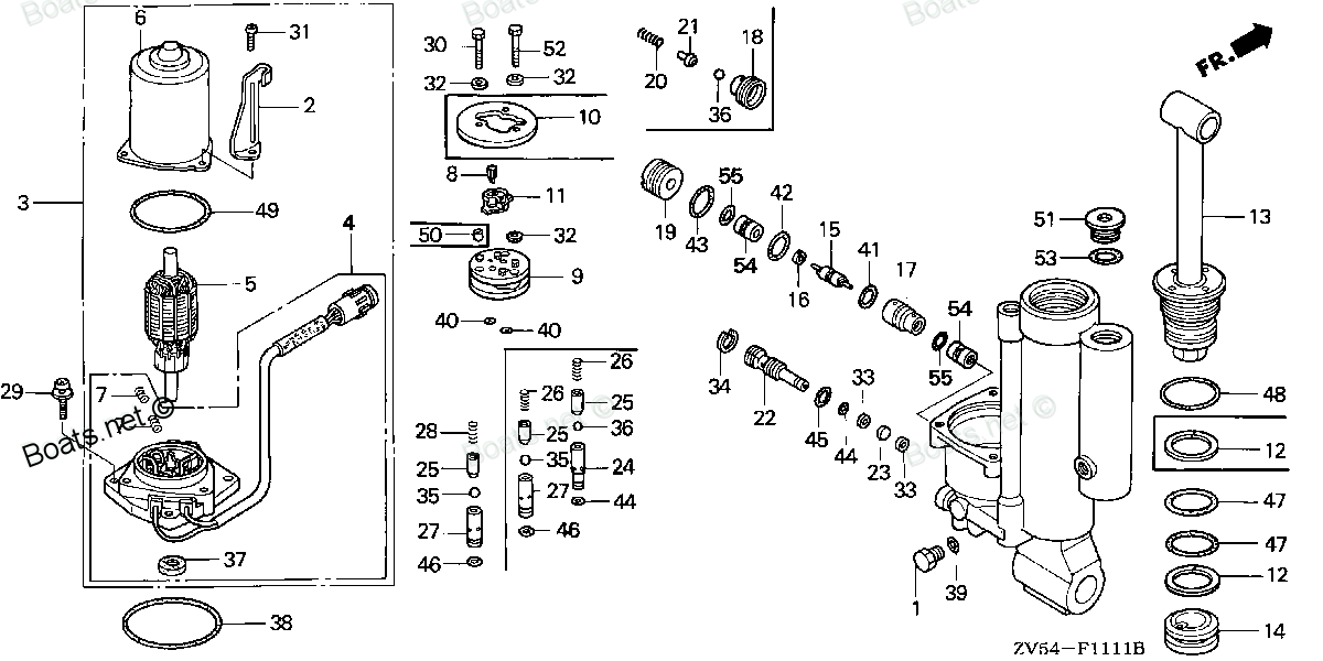
56161-ZV5-821 SLEEVE (Honda Code 4594586). Honda
BF35AM LRTA, BF35AM XRTA, BF40AW LHTA, BF40AW LRTA, BF40AW XRTA, BF45AM LRTA, BF45AM SRTA, BF45AM XRTA, BF50AW LHTA, BF50AW LRTA, BF50AW XRTA
SLEEVE
. Honda parts")
Price: query
Rating:
Number on catalog scheme: 17
Compatible models:
Honda entire parts catalog list:
- POWER TILT COMPONENTS » 56161-ZV5-821
- POWER TILT COMPONENTS » 56161-ZV5-821
- POWER TILT COMPONENTS » 56161-ZV5-821
- POWER TILT COMPONENTS » 56161-ZV5-821
- POWER TILT COMPONENTS » 56161-ZV5-821
- POWER TILT COMPONENTS » 56161-ZV5-821
- POWER TILT COMPONENTS » 56161-ZV5-821
- POWER TILT COMPONENTS » 56161-ZV5-821
- POWER TILT COMPONENTS » 56161-ZV5-821
- POWER TILT COMPONENTS » 56161-ZV5-821
- POWER TILT COMPONENTS » 56161-ZV5-821
Information:
Table 1
Required Tools
Tool Part Number Part Description Qty
A 370-8376 Capping Kit 1
Ensure that all adjustments and repairs that are carried out to the fuel system are performed by authorized personnel that have the correct training.Before beginning ANY work on the fuel system, refer to Operation and Maintenance Manual, "General Hazard Information and High Pressure Fuel Lines" for safety information. Refer to System Operation, Testing and Adjusting, "Cleanliness of Fuel System Components" for detailed information on the standards of cleanliness that must be observed during ALL work on the fuel system.
Care must be taken to ensure that fluids are contained during performance of inspection, maintenance, testing, adjusting and repair of the product. Be prepared to collect the fluid with suitable containers before opening any compartment or disassembling any component containing fluids.Dispose of all fluids according to local regulations and mandates.
Turn the fuel supply to the OFF position.
Turn the battery disconnect switch to the OFF position.
Drain the secondary filters. Refer to Operation and Maintenance Manual, "Fuel System Secondary Filter - Replace" for the correct procedure.
Illustration 1 g03389540
Typical example
Make temporary identification marks on all the plastic tube assemblies in order to show the correct position of the tube assemblies.
Place a suitable container below the fuel filter base in order to catch any fuel that might be spilled.
Disconnect plastic tube assembly (1), plastic tube assembly (2), and plastic tube assembly (3) from the fuel filter base.
Use Tooling (A) in order to plug the plastic tube assemblies. Use Tooling (A) in order to cap the ports in the fuel filter base.
Illustration 2 g03389546
Typical example
Remove secondary filters (6) from canisters (7). Refer to Operation and Maintenance Manual, "Fuel System Secondary Filter - Replace" for the correct procedure.
Remove bolts (4) from fuel filter base (5). Remove the fuel filter base from the mounting bracket. Note: Do not disassemble the fuel filter base.Installation Procedure
Ensure that all adjustments and repairs that are carried out to the fuel system are performed by authorized personnel that have the correct training.Before beginning ANY work on the fuel system, refer to Operation and Maintenance Manual, "General Hazard Information and High Pressure Fuel Lines" for safety information. Refer to System Operation, Testing and Adjusting , "Cleanliness of Fuel System Components" for detailed information on the standards of cleanliness that must be observed during ALL work on the fuel system.
Illustration 3 g03389546
Typical example
Ensure that fuel filter base (5) is clean and free from damage. If necessary, replace the complete fuel filter base and filter assembly.
Position fuel filter base (5) on the mounting bracket. Install bolts (4). Tighten the bolts to a torque of 44 N m (32 lb ft).
If necessary, install new fuel filters (6) to canisters (7). Refer to Operation and Maintenance Manual, "Fuel System Secondary Filter - Replace" for the correct procedure.
Illustration 4 g03389540
Typical example
Remove the plugs from the plastic tube assemblies. Remove the caps from the ports in the fuel filter base.
Ensure that the plastic tube assemblies are installed in the original positions. Failure to connect the plastic tube assemblies to the correct ports will allow contamination to enter the fuel system. Serious damage to the engine will result if contaminated fuel enters the fuel system.
Connect plastic tube assembly (1), plastic tube assembly (2), and plastic tube assembly (3) to fuel filter base (5).
Turn the fuel supply to the ON position.
Turn the battery disconnect switch to the ON position. End By:
Remove the air from the fuel system. Refer to Operation and Maintenance Manual, "Fuel System - Prime" for the correct procedure.
Parts sleeve Honda:
56161-ZV5-822
56161-ZV5-822 SLEEVE (Honda Code 6012967).
BF40A1 LHTA, BF40A1 LRTA, BF40A1 XRTA, BF40A2 LHTA, BF40A2 LRTA, BF40A2 XRTA, BF40A3 LHTA, BF40A3 LRTA, BF40A3 XRTA, BF40AW LHTA, BF40AW LRTA, BF40AX LHTA, BF40AX LRTA, BF40AX XRTA, BF40AY LHTA, BF40AY LRTA, BF40AY XRTA, BF50A1 LHTA, BF50A1 LRTA, BF5