24122-ZV5-000 SLIDER, SHIFT (Honda Code 3702818). Honda
BF35AM LHA, BF35AM LRA, BF35AM LRTA, BF35AM SHA, BF35AM XRTA, BF40A1 LHA, BF40A1 LHTA, BF40A1 LRA, BF40A1 LRTA, BF40A1 XRTA, BF40A2 LHA, BF40A2 LHTA, BF40A2 LRA, BF40A2 LRTA, BF40A2 XRTA, BF40A3 LHA, BF40A3 LHTA, BF40A3 LRA, BF40A3 LRTA, BF40A3 XRTA,
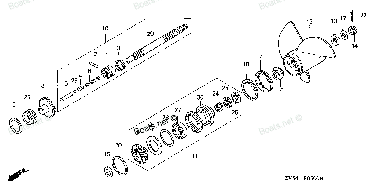
SLIDER
. Honda parts")
Price: query
Rating:
You can buy parts:
As an associate, we earn commssions on qualifying purchases through the links below

$24.94
17-07-2024
0.3125[0.14] Pounds
US: PowerToolReplacement
Honda 24122-ZV5-000 Slider Shift
Honda Genuine Honda part that fits your specific vehicle || Slider Shift || Part Number: 24122-ZV5-000 || Manufactured to meet specifications for fit, form, and function
Honda Genuine Honda part that fits your specific vehicle || Slider Shift || Part Number: 24122-ZV5-000 || Manufactured to meet specifications for fit, form, and function
Number on catalog scheme: 5
Compatible models:
BF35AM LHA
BF35AM LRA
BF35AM LRTA
BF35AM SHA
BF35AM XRTA
BF40A1 LHA
BF40A1 LHTA
BF40A1 LRA
BF40A1 LRTA
BF40A1 XRTA
BF40A2 LHA
BF40A2 LHTA
BF40A2 LRA
BF40A2 LRTA
BF40A2 XRTA
BF40A3 LHA
BF40A3 LHTA
BF40A3 LRA
BF40A3 LRTA
BF40A3 XRTA
BF40A4 LHA
BF40A4 LHTA
BF40A4 LRTA
BF40A5 LHA
BF40A5 LHTA
BF40A5 LRTA
BF40A6 LHA
BF40A6 LHTA
BF40A6 LRTA
BF40AK0 LHA
BF40AK0 LRTA
BF40AW LHA
BF40AW LHTA
BF40AW LRA
BF40AW LRTA
BF40AW XRTA
BF40AX LHA
BF40AX LHTA
BF40AX LRA
BF40AX LRTA
BF40AX XRTA
BF40AY LHA
BF40AY LHTA
BF40AY LRA
BF40AY LRTA
BF40AY XRTA
BF40DK2 LHA
BF40DK2 LRTA
BF45AM LHA
BF45AM LRA
BF45AM LRTA
BF45AM SRTA
BF45AM XRTA
BF50A1 LHTA
BF50A1 LRA
BF50A1 LRTA
BF50A1 XRTA
BF50A2 LHTA
BF50A2 LRA
BF50A2 LRTA
BF50A2 XRTA
BF50A3 LHTA
BF50A3 LRA
BF50A3 LRTA
BF50A3 XRTA
BF50A4 LHTA
BF50A4 LRTA
BF50A4 XRTA
BF50A5 LHTA
BF50A5 LRTA
BF50A5 XRTA
BF50A6 LHTA
BF50A6 LRTA
BF50A6 XRTA
BF50AK0 LRTA
BF50AK0 XRTA
BF50AW LHTA
BF50AW LRA
BF50AW LRTA
BF50AW XRTA
BF50AX LHTA
BF50AX LRA
BF50AX LRTA
BF50AX XRTA
BF50AY LHTA
BF50AY LRA
BF50AY LRTA
BF50AY XRTA
BF50DK2 LRTA
BF50DK2 XRTA
Honda
Honda entire parts catalog list:
- PROPELLER » 24122-ZV5-000
- PROPELLER » 24122-ZV5-000
- PROPELLER » 24122-ZV5-000
- PROPELLER » 24122-ZV5-000
- PROPELLER » 24122-ZV5-000
- PROPELLER » 24122-ZV5-000
- PROPELLER » 24122-ZV5-000
- PROPELLER » 24122-ZV5-000
- PROPELLER » 24122-ZV5-000
- PROPELLER » 24122-ZV5-000
- PROPELLER » 24122-ZV5-000
- PROPELLER » 24122-ZV5-000
- PROPELLER » 24122-ZV5-000
- PROPELLER » 24122-ZV5-000
- PROPELLER » 24122-ZV5-000
- PROPELLER » 24122-ZV5-000
- PROPELLER » 24122-ZV5-000
- PROPELLER » 24122-ZV5-000
- PROPELLER » 24122-ZV5-000
- PROPELLER » 24122-ZV5-000
- PROPELLER PROPELLER SHAFT » 24122-ZV5-000
- PROPELLER PROPELLER SHAFT » 24122-ZV5-000
- PROPELLER PROPELLER SHAFT » 24122-ZV5-000
- PROPELLER PROPELLER SHAFT » 24122-ZV5-000
- PROPELLER PROPELLER SHAFT » 24122-ZV5-000
- PROPELLER PROPELLER SHAFT » 24122-ZV5-000
- PROPELLER PROPELLER SHAFT » 24122-ZV5-000
- PROPELLER PROPELLER SHAFT » 24122-ZV5-000
- PROPELLER PROPELLER SHAFT » 24122-ZV5-000
- PROPELLER PROPELLER SHAFT » 24122-ZV5-000
- PROPELLER PROPELLER SHAFT » 24122-ZV5-000
- PROPELLER » 24122-ZV5-000
- PROPELLER » 24122-ZV5-000
- PROPELLER » 24122-ZV5-000
- PROPELLER » 24122-ZV5-000
- PROPELLER » 24122-ZV5-000
- PROPELLER » 24122-ZV5-000
- PROPELLER » 24122-ZV5-000
- PROPELLER » 24122-ZV5-000
- PROPELLER » 24122-ZV5-000
- PROPELLER » 24122-ZV5-000
- PROPELLER » 24122-ZV5-000
- PROPELLER » 24122-ZV5-000
- PROPELLER » 24122-ZV5-000
- PROPELLER » 24122-ZV5-000
- PROPELLER » 24122-ZV5-000
- PROPELLER SHAFT » 24122-ZV5-000
- PROPELLER SHAFT » 24122-ZV5-000
- PROPELLER » 24122-ZV5-000
- PROPELLER » 24122-ZV5-000
- PROPELLER » 24122-ZV5-000
- PROPELLER » 24122-ZV5-000
- PROPELLER » 24122-ZV5-000
- PROPELLER » 24122-ZV5-000
- PROPELLER » 24122-ZV5-000
- PROPELLER » 24122-ZV5-000
- PROPELLER » 24122-ZV5-000
- PROPELLER » 24122-ZV5-000
- PROPELLER » 24122-ZV5-000
- PROPELLER » 24122-ZV5-000
- PROPELLER » 24122-ZV5-000
- PROPELLER » 24122-ZV5-000
- PROPELLER » 24122-ZV5-000
- PROPELLER » 24122-ZV5-000
- PROPELLER » 24122-ZV5-000
- PROPELLER PROPELLER SHAFT » 24122-ZV5-000
- PROPELLER PROPELLER SHAFT » 24122-ZV5-000
- PROPELLER PROPELLER SHAFT » 24122-ZV5-000
- PROPELLER PROPELLER SHAFT » 24122-ZV5-000
- PROPELLER PROPELLER SHAFT » 24122-ZV5-000
- PROPELLER PROPELLER SHAFT » 24122-ZV5-000
- PROPELLER PROPELLER SHAFT » 24122-ZV5-000
- PROPELLER PROPELLER SHAFT » 24122-ZV5-000
- PROPELLER PROPELLER SHAFT » 24122-ZV5-000
- PROPELLER PROPELLER SHAFT » 24122-ZV5-000
- PROPELLER PROPELLER SHAFT » 24122-ZV5-000
- PROPELLER » 24122-ZV5-000
- PROPELLER » 24122-ZV5-000
- PROPELLER » 24122-ZV5-000
- PROPELLER » 24122-ZV5-000
- PROPELLER » 24122-ZV5-000
- PROPELLER » 24122-ZV5-000
- PROPELLER » 24122-ZV5-000
- PROPELLER » 24122-ZV5-000
- PROPELLER » 24122-ZV5-000
- PROPELLER » 24122-ZV5-000
- PROPELLER » 24122-ZV5-000
- PROPELLER » 24122-ZV5-000
- PROPELLER SHAFT » 24122-ZV5-000
- PROPELLER SHAFT » 24122-ZV5-000
Information:
Table 1
Required Tools
Tool Part Number Part Description Qty
B - LASER 4920
1/2 Inch Drive HP Fuel Line Socket Set 1
Ensure that all adjustments and repairs that are carried out to the fuel system are performed by authorized personnel that have the correct training.Before beginning ANY work on the fuel system, refer to Operation and Maintenance Manual, "General Hazard Information and High Pressure Fuel Lines" for safety information. Refer to System Operation, Testing and Adjusting, "Cleanliness of Fuel System Components" for detailed information on the standards of cleanliness that must be observed during ALL work on the fuel system.
Note: The following procedure should be adopted in order to install the fuel injection lines when the electronic unit injectors or the fuel manifold have not been removed. If the electronic unit injectors or the fuel manifold have been removed, refer to Disassembly and Assembly, "Electronic Unit Injector - Install" and Disassembly and Assembly, "Fuel Manifold - Install" for more information.
Illustration 1 g02699457
Illustration 2 g02849442
Remove the relevant plug from fuel manifold (24) and fuel injection pump (29).
Remove the caps from new fuel injection line (28).
Position fuel injection line (28) onto fuel injection pump (29) and fuel manifold (24). Loosely install nuts for the fuel injection line onto the fuel manifold and the fuel injection pump.
Use Tooling (B) to tighten the nuts on fuel injection line (23) to a torque of 25 N m (221 lb in). Note: Ensure that fuel injection lines do not contact any other engine component.
Remove the caps from the port of the electronic unit injector and from the appropriate port in fuel manifold (16).
Loosely connect the nuts at both ends of fuel injection line (12) to the electronic unit injector and to the appropriate port in fuel manifold (16). Ensure that the ends of the fuel injection line are correctly seated in the electronic unit injector and in the fuel manifold.
Repeat Step 5 through Step 6 in order to install the remaining fuel injection lines.
Position clamp (22) onto fuel injection lines (12) and install clamp bolt (20). Tighten the bolt to a torque of 10 N m (89 lb in). Note: Ensure that the rubber separator is correctly installed around the fuel injection lines. Ensure that fuel injection lines do not contact any other engine component.
Repeat Step 8 for the remaining fuel injection lines.
Use Tooling (B) to tighten the nuts on fuel injection line (12) to a torque of 25 N m (221 lb in).
Position bracket (25) onto the valve mechanism cover. Install bolt (26) and tighten the bolt to a torque of 10 N m (89 lb in).
If necessary, reinstall the front engine lifting eye (31). Install bolts (30) and tighten the bolts to a torque of 45 N m (33 lb ft).
Illustration 3 g02849446
Illustration 4 g02699461
Illustration 5 g02699462
Position bracket (19) onto the valve mechanism cover. Install bolts (20) and tighten the bolts to a torque of 25 N m (221 lb in).
Install the fuel filter base mounting bracket (21) (not shown). Refer to Disassembly and Assembly, "Fuel Filter Base - Remove and Install" for the correct procedure.
Position the wiring harness assembly (11) over fuel injection lines (12).
Install bolt (6) to wiring harness assembly (11). Tighten the bolt to a torque of 10 N m (89 lb in)
Install cable straps (1) to the wiring harness and brackets (25). Ensure that the cable straps meet the Original Equipment Manufactures (OEM) specifications.
Connect wiring harness assembly (9) to fuel metering valve (10). Slide the locking tab for wiring harness assembly (9) into the locked position.
Connect wiring harness assembly (14) to oil pressure switch (13).
Connect wiring harness assembly (3) to pressure sensor (2). Slide the locking tab for wiring harness assembly (3) into the locked position.
Connect wiring harness assembly to fuel temperature sensor (4). Slide the locking tab for wiring harness assembly into the locked position.
Connect wiring harness assembly (15) to crankshaft position sensor (16). Slide the locking tab for wiring harness assembly (15) into the locked position.
Connect wiring harness assembly (17) to camshaft position sensor (18). Slide the locking tab for wiring harness assembly (17) into the locked position.
Install cable straps to the wiring harness assembly in the relevant positions. Ensure that the cable straps meet the OEM specifications.
Install the OEM wiring harness assembly to connection (5) and connection (8).
If necessary, install the Diesel Particulate Filter (DPF). Refer to Disassembly and Assembly, "Diesel Particulate Filter - Install" for the correct procedure.
Turn the fuel supply to the ON position.
Turn the battery disconnect switch to the ON position.
Remove trapped air from the fuel system. Refer to the Operation and Maintenance Manual, "Fuel System - Prime" for the correct procedure.