50539-ZW4-H10 SPACER (19.4X6) (Honda Code 7459530). Honda
BF40A4 LHTA, BF40A4 LRTA, BF40A5 LHTA, BF40A5 LRTA, BF40A6 LHTA, BF40A6 LRTA, BF40AK0 LRTA, BF40DK2 LRTA, BF50A4 LHTA, BF50A4 LRTA, BF50A4 SRJA, BF50A4 XRTA, BF50A5 LHTA, BF50A5 LRTA, BF50A5 SRJA, BF50A5 XRTA, BF50A6 LHTA, BF50A6 LRTA, BF50A6 SRJA, B
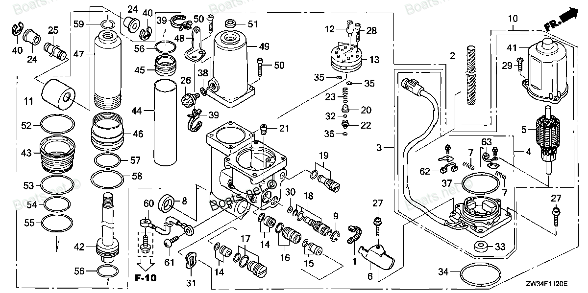
SPACER
 (Honda Code 7459530). Honda parts")
Price: query
Rating:
You can buy parts:
As an associate, we earn commssions on qualifying purchases through the links below

$14.14
18-06-2024
0.1875[0.08] pounds
US: PowerToolReplacement
Honda 50539-ZW4-H10 Spacer (19.4X6)
Honda Genuine, OEM Honda Replacement Part || Honda replacement spacer (19.4x6), part number 50539-ZW4-H10
Honda Genuine, OEM Honda Replacement Part || Honda replacement spacer (19.4x6), part number 50539-ZW4-H10
Number on catalog scheme: 8
Compatible models:
BF40A4 LHTA
BF40A4 LRTA
BF40A5 LHTA
BF40A5 LRTA
BF40A6 LHTA
BF40A6 LRTA
BF40AK0 LRTA
BF40DK2 LRTA
BF50A4 LHTA
BF50A4 LRTA
BF50A4 SRJA
BF50A4 XRTA
BF50A5 LHTA
BF50A5 LRTA
BF50A5 SRJA
BF50A5 XRTA
BF50A6 LHTA
BF50A6 LRTA
BF50A6 SRJA
BF50A6 XRTA
BF50AK0 LRTA
BF50AK0 SRJA
BF50AK0 XRTA
BF50DK2 LRTA
BF50DK2 XRTA
Honda
Honda entire parts catalog list:
- POWER TRIM-TILT » 50539-ZW4-H10
- POWER TRIM-TILT » 50539-ZW4-H10
- POWER TRIM-TILT » 50539-ZW4-H10
- POWER TRIM-TILT » 50539-ZW4-H10
- POWER TRIM-TILT » 50539-ZW4-H10
- POWER TRIM-TILT » 50539-ZW4-H10
- POWER TRIM-TILT » 50539-ZW4-H10
- POWER TRIM-TILT » 50539-ZW4-H10
- POWER TRIM-TILT » 50539-ZW4-H10
- POWER TRIM-TILT » 50539-ZW4-H10
- POWER TRIM-TILT » 50539-ZW4-H10
- POWER TRIM-TILT » 50539-ZW4-H10
- POWER TRIM-TILT » 50539-ZW4-H10
- POWER TRIM-TILT » 50539-ZW4-H10
- POWER TRIM-TILT » 50539-ZW4-H10
- POWER TRIM-TILT » 50539-ZW4-H10
- POWER TRIM-TILT » 50539-ZW4-H10
- POWER TRIM-TILT » 50539-ZW4-H10
- POWER TRIM-TILT » 50539-ZW4-H10
- POWER TRIM-TILT » 50539-ZW4-H10
- POWER TRIM-TILT » 50539-ZW4-H10
- POWER TRIM-TILT » 50539-ZW4-H10
- POWER TRIM-TILT » 50539-ZW4-H10
- POWER TRIM-TILT » 50539-ZW4-H10
- POWER TRIM-TILT » 50539-ZW4-H10
Information:
1. Remove suction pipe (2) and support (1) from the engine as a unit.2. Remove the ring of carbon from the top inner surface of the cylinders with tool (A).3. Turn the crankshaft until two pistons are at bottom center. 4. Remove connecting rod caps (3) from the two connecting rods.
Do not let the connecting rods hit the bottom edge of the cylinder bores or the crankshaft during removal and installation of the pistons.
5. Push the piston and connecting rod away from the crankshaft until the piston rings are above the cylinder block. 6. Remove the two pistons (4) and the connecting rods. Keep each connecting rod cap with its respective connecting rod and piston. Put identification on each connecting rod as to its location for use at assembly.7. Do Steps 3 through 6 for the remainder of the pistons.Install Pistons
1. Turn the crankshaft until the bearing journal for the pistons to be installed is at bottom center.2. Put clean engine oil on the crankshaft bearing journal and inside of the cylinder walls. Put clean engine oil on the piston rings and connecting rod bearings. 3. Make sure the ring gaps are approximately 120° apart. Install tool (A) on the piston.4. Put the piston in position in the same cylinder bore from which it was removed. The hole (crater) in the top of the piston must be toward (nearest) the center of the engine.5. Push the piston into place while putting the connecting rod into position on the crankshaft.6. Put clean engine oil on the threads of the bolts and contact surfaces of the nuts for the connecting rod caps.
When installing connecting rod caps, make sure that the numbers on the side of the cap is next to and respective with the number on the side of the connecting rod.
7. Put the cap in position on the connecting rod and install the nuts. Tighten the nuts to a torque of 30 3 lb.ft. (4.1 0.4 mkg). Put a mark on each nut and the end of each bolt. Tighten the nuts 60 5° more.8. Follow the same above procedure for installation of the remainder of the pistons.9. Install the suction pipe and support as a unit.end by: a) install oil panb) install cylinder headsDisassemble Pistons
start by: a) remove pistons 1. Remove the rings from the piston with tool (A). 2. Remove snap ring (2), pin (1), and connecting rod (3) from the piston.Assemble Pistons
1. Install connecting rod (1) in the piston with boss (2) on the same side as the hole (crater) in the top of the piston.2. Install piston pin (3) and snap ring (4). 3. When old pistons are to be used, clean the piston grooves with tool (A).4. Install the spring for the oil ring. Install the oil ring with tool (B). The gap in the ring must be approximately 180° from the oil ring spring connection.5. Install the compression ring using tool (B). The side of the ring having identification "TOP" must be toward top of piston. The gaps in the rings must be approximately 120° apart. Compression rings not having identification must be installed with the edge having a bevel toward the top of the piston.end by: a) install pistons
Parts spacer Honda:
58151-ZV5-000

58151-ZV5-000 SPACER (10MM) (Honda Code 3705209).
BF35AM LHA, BF35AM LRA, BF35AM LRTA, BF35AM SHA, BF35AM XRTA, BF40A1 LHA, BF40A1 LHTA, BF40A1 LRA, BF40A1 LRTA, BF40A1 XRTA, BF40A2 LHA, BF40A2 LHTA, BF40A2 LRA, BF40A2 LRTA, BF40A2 XRTA, BF40A3 LHA, BF40A3 LHTA, BF40A3 LRA, BF40A3 LRTA, BF40A3 XRTA,
24885-ZV5-000

24885-ZV5-000 SPACER, REMOTE CONTROL BOX (Honda Code 3703303).
BF115A1 LA, BF115A1 LCA, BF115A1 XA, BF115A1 XCA, BF115A2 LA, BF115A2 LCA, BF115A2 XA, BF115A2 XCA, BF115A3 LA, BF115A3 LCA, BF115A3 XA, BF115A3 XCA, BF115A4 LA, BF115A4 LCA, BF115A4 XA, BF115A4 XCA, BF115A5 LA, BF115A5 LCA, BF115A5 XA, BF115A5 XCA,
24887-ZV5-000

24887-ZV5-000 SPACER, CLICK SPRING (Honda Code 3703311).
BF115A1 LA, BF115A1 LCA, BF115A1 XA, BF115A1 XCA, BF115A2 LA, BF115A2 LCA, BF115A2 XA, BF115A2 XCA, BF115A3 LA, BF115A3 LCA, BF115A3 XA, BF115A3 XCA, BF115A4 LA, BF115A4 LCA, BF115A4 XA, BF115A4 XCA, BF115A5 LA, BF115A5 LCA, BF115A5 XA, BF115A5 XCA,
24894-ZV5-000
24894-ZV5-000 SPACER, NEUTRAL SWITCH (Honda Code 3703345).
BF115A1 LA, BF115A1 LCA, BF115A1 XA, BF115A1 XCA, BF115A2 LA, BF115A2 LCA, BF115A2 XA, BF115A2 XCA, BF115A3 LA, BF115A3 LCA, BF115A3 XA, BF115A3 XCA, BF115A4 LA, BF115A4 LCA, BF115A4 XA, BF115A4 XCA, BF115A5 LA, BF115A5 LCA, BF115A5 XA, BF115A5 XCA,
24898-ZV5-000
24898-ZV5-000 SPACER, CABLE CLAMP (Honda Code 3703378).
BF115A1 LA, BF115A1 LCA, BF115A1 XA, BF115A1 XCA, BF115A2 LA, BF115A2 LCA, BF115A2 XA, BF115A2 XCA, BF115A3 LA, BF115A3 LCA, BF115A3 XA, BF115A3 XCA, BF115A4 LA, BF115A4 LCA, BF115A4 XA, BF115A4 XCA, BF115A5 LA, BF115A5 LCA, BF115A5 XA, BF115A5 XCA,
24832-ZW5-U01
24832-ZW5-U01 SPACER, CABLE CLAMP (Honda Code 6799712).
BF115A1 LA, BF115A1 LCA, BF115A1 XA, BF115A1 XCA, BF115A2 LA, BF115A2 LCA, BF115A2 XA, BF115A2 XCA, BF115A3 LA, BF115A3 LCA, BF115A3 XA, BF115A3 XCA, BF115A4 LA, BF115A4 LCA, BF115A4 XA, BF115A4 XCA, BF115A5 LA, BF115A5 LCA, BF115A5 XA, BF115A5 XCA,
06241-ZW5-U10
06241-ZW5-U10 SPACER, TOP DUAL (Honda Code 6796197).
BF115A1 LA, BF115A1 LCA, BF115A1 XA, BF115A1 XCA, BF115A2 LA, BF115A2 LCA, BF115A2 XA, BF115A2 XCA, BF115A3 LA, BF115A3 LCA, BF115A3 XA, BF115A3 XCA, BF115A4 LA, BF115A4 LCA, BF115A4 XA, BF115A4 XCA, BF115A5 LA, BF115A5 LCA, BF115A5 XA, BF115A5 XCA,
06241-ZW5-U00
06241-ZW5-U00 SPACER, TOP SINGLE (Honda Code 6796189).
BF115A1 LA, BF115A1 LCA, BF115A1 XA, BF115A1 XCA, BF115A2 LA, BF115A2 LCA, BF115A2 XA, BF115A2 XCA, BF115A3 LA, BF115A3 LCA, BF115A3 XA, BF115A3 XCA, BF115A4 LA, BF115A4 LCA, BF115A4 XA, BF115A4 XCA, BF115A5 LA, BF115A5 LCA, BF115A5 XA, BF115A5 XCA,