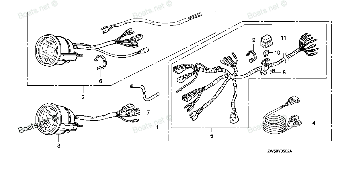
06373-ZY3-800 SPEEDOMETER KIT (DIGITAL)(USA) (Honda Code 7632813). (USE FOR 32540-ZY3-800/801) Honda
BF115A4 LA, BF115A4 XA, BF115A5 LA, BF115A5 LCA, BF115A5 XA, BF115A5 XCA, BF115A6 LA, BF115A6 LCA, BF115A6 XA, BF115A6 XCA, BF115AK0 LA, BF115AK0 XA, BF130A4 LA, BF130A4 LCA, BF130A4 XA, BF130A4 XCA, BF135A4 LA, BF135A4 XA, BF135A4 XCA, BF135A5 LA, B
SPEEDOMETER
(USA) (Honda Code 7632813). (USE FOR 32540-ZY3-800/801) Honda parts")
Price: query
Rating:
Number on catalog scheme: 2
Compatible models:
BF115A4 LA
BF115A4 XA
BF115A5 LA
BF115A5 LCA
BF115A5 XA
BF115A5 XCA
BF115A6 LA
BF115A6 LCA
BF115A6 XA
BF115A6 XCA
BF115AK0 LA
BF115AK0 XA
BF130A4 LA
BF130A4 LCA
BF130A4 XA
BF130A4 XCA
BF135A4 LA
BF135A4 XA
BF135A4 XCA
BF135A5 LA
BF135A5 XA
BF135A5 XCA
BF135A6 LA
BF135A6 XA
BF135A6 XCA
BF135AK0 LA
BF135AK0 XA
BF135AK0 XCA
BF150A4 LA
BF150A4 XA
BF150A4 XCA
BF150A5 LA
BF150A5 XA
BF150A5 XCA
BF150A6 LA
BF150A6 XA
BF150A6 XCA
BF150AK0 LA
BF150AK0 XA
BF150AK0 XCA
BF200A4 LA
BF200A4 XA
BF200A4 XCA
BF200A4 XXA
BF200A4 XXCA
BF200A5 LA
BF200A5 XA
BF200A5 XCA
BF200A5 XXA
BF200A5 XXCA
BF200A6 LA
BF200A6 XA
BF200A6 XCA
BF200A6 XXA
BF200A6 XXCA
BF200AK0 LA
BF200AK0 XA
BF200AK0 XCA
BF225A4 LA
BF225A4 XA
BF225A4 XCA
BF225A4 XXA
BF225A4 XXCA
BF225A5 LA
BF225A5 XA
BF225A5 XCA
BF225A5 XXA
BF225A5 XXCA
BF225A6 LA
BF225A6 XA
BF225A6 XCA
BF225A6 XXA
BF225A6 XXCA
BF225AK0 LA
BF225AK0 XA
BF225AK0 XCA
BF225AK0 XXA
BF225AK0 XXCA
BF75DK0 LHTA
BF75DK0 LRTA
BF90DK0 LHTA
BF90DK0 LRTA
BF90DK0 XRTA
Honda
Honda entire parts catalog list:
- METER (DIGITAL) » 06373-ZY3-800
- METER (DIGITAL) » 06373-ZY3-800
- METER (DIGITAL) » 06373-ZY3-800
- METER (DIGITAL) » 06373-ZY3-800
- METER (DIGITAL) » 06373-ZY3-800
- METER (DIGITAL) » 06373-ZY3-800
- METER (DIGITAL) » 06373-ZY3-800
- METER (DIGITAL) » 06373-ZY3-800
- METER (DIGITAL) » 06373-ZY3-800
- METER (DIGITAL) » 06373-ZY3-800
- METER (DIGITAL) » 06373-ZY3-800
- METER (DIGITAL) » 06373-ZY3-800
- METER (DIGITAL) » 06373-ZY3-800
- METER (DIGITAL) » 06373-ZY3-800
- METER (DIGITAL) » 06373-ZY3-800
- METER (DIGITAL) » 06373-ZY3-800
- METER (3) » 06373-ZY3-800
- METER (3) » 06373-ZY3-800
- METER (3) » 06373-ZY3-800
- METER (3) » 06373-ZY3-800
- METER (3) » 06373-ZY3-800
- METER (3) » 06373-ZY3-800
- METER (3) » 06373-ZY3-800
- METER (3) » 06373-ZY3-800
- METER (3) » 06373-ZY3-800
- METER (3) » 06373-ZY3-800
- METER (3) » 06373-ZY3-800
- METER (3) » 06373-ZY3-800
- METER (3) » 06373-ZY3-800
- METER (3) » 06373-ZY3-800
- METER (3) » 06373-ZY3-800
- METER (3) » 06373-ZY3-800
- METER (3) » 06373-ZY3-800
- METER (3) » 06373-ZY3-800
- METER (3) » 06373-ZY3-800
- METER (3) » 06373-ZY3-800
- METER (3) » 06373-ZY3-800
- METER (3) » 06373-ZY3-800
- METER (3) » 06373-ZY3-800
- METER (3) » 06373-ZY3-800
- METER (2) » 06373-ZY3-800
- METER (2) » 06373-ZY3-800
- METER (2) » 06373-ZY3-800
- METER (2) » 06373-ZY3-800
- METER (2) » 06373-ZY3-800
- METER (2) » 06373-ZY3-800
- METER (2) » 06373-ZY3-800
- METER (2) » 06373-ZY3-800
- METER (2) » 06373-ZY3-800
- METER (2) » 06373-ZY3-800
- METER (1) » 06373-ZY3-800
- METER (1) » 06373-ZY3-800
- METER (1) » 06373-ZY3-800
- METER (1) » 06373-ZY3-800
- METER (1) » 06373-ZY3-800
- METER (1) » 06373-ZY3-800
- METER (1) » 06373-ZY3-800
- METER (1) » 06373-ZY3-800
- METER (2) » 06373-ZY3-800
- METER (2) » 06373-ZY3-800
- METER (2) » 06373-ZY3-800
- METER (2) » 06373-ZY3-800
- METER (2) » 06373-ZY3-800
- METER (2) » 06373-ZY3-800
- METER (2) » 06373-ZY3-800
- METER (2) » 06373-ZY3-800
- METER (2) » 06373-ZY3-800
- METER (2) » 06373-ZY3-800
- METER (1) » 06373-ZY3-800
- METER (1) » 06373-ZY3-800
- METER (1) » 06373-ZY3-800
- METER (1) » 06373-ZY3-800
- METER (1) » 06373-ZY3-800
- METER (1) » 06373-ZY3-800
- METER (1) » 06373-ZY3-800
- METER (1) » 06373-ZY3-800
- METER (1) » 06373-ZY3-800
- METER (1) » 06373-ZY3-800
- SPEEDOMETER KIT (DIGITAL) » 06373-ZY3-800
- SPEEDOMETER KIT (DIGITAL) » 06373-ZY3-800
- SPEEDOMETER KIT (DIGITAL) » 06373-ZY3-800
- SPEEDOMETER KIT (DIGITAL) » 06373-ZY3-800
- SPEEDOMETER KIT (DIGITAL) » 06373-ZY3-800
Information:
(1) Figure indicates a nominal size of automotive low-tension line (JIS C 3406).(2) This schematic shows the electrical system of the standard engine equipped with a key shut down solenoid and glow plugs.<Solenoid ETR type> (1) Figure indicates a nominal size of automotive low-tension line (JIS C 3406).(2) This schematic shows the electrical system of the standard engine equipped with a key shut down solenoid and glow plugs.2. Specifications (standard) STARTER
1. Disassembly
Disassembly sequence1 Pinion set2 Solenoid switch3 Rear bracket4 Brush holder5 Yoke6 Armature7 Ball bearing8 Ball9 Seal set10 Reduction gears11 Lever set12 Washer set13 Gear shaft14 Internal gear15 Overrunning clutch16 Front bracket
The pinion must be removed before removal or replacement of the following parts:a) Front bracketb) Reduction gearsc) Overrunning clutch
(1) Removing Pinion The pinion can be removed when it is held in the pushed-out position during energization of the solenoid switch. Disconnect the M-terminal connector and make a circuit that connects the starter motor and the battery as shown in the drawing. Close switches S1 and S2 to make the pinion come out and rotate. Then, open switch S2. The pinion will stop rotating but will stay in the pushed-out position. Apply a pipe-shaped implement to the pinion stopper and lightly tap it with a hammer to remove the pinion. If the pinion returns to the retracted position before disengagement of the stopper while the tool is being tapped, repeat the procedure from the beginning.(2) BallThe ball at the end of the armature acts as a bearing for movement of the armature in the thrust direction. When the armature is removed, the ball may stick to the grease on it. Be careful not to lose the ball.2. Inspection(1) Armature (a) Coil Short Circuit TestPlace the armature on a growler tester. Hold an iron rod parallel with the armature and slowly rotate the armature by hand. If the iron rod vibrates or is pulled toward the armature, the armature has a short-circuited coil and must be replaced.(b) Coil Ground TestCheck whether continuity exists between the commutator and shaft (or core). If continuity exists, the coil is grounded and the armature must be replaced. (c) Commutator Inspection1) Measure the commutator's runout using a dial gauge. If the measurement exceeds the specified limit, rectify the problem, making sure that the outside diameter stays within specification. If the surface is rough or has stepped wear, rectify the problem with emery paper (#300 - 500).
Unit: mm (in.) 2) Measure the commutator's outside diameter. If the measurement is out of specification, replace the armature.
Unit: mm (in.) 3) Measure the molding undercut depth between segments. If the depth is smaller than the limit, cut the molding to a depth of 0.4-0.6 mm (0.016-0.024 in.). (2) Field Coil (a) Coil Open Circuit TestCheck whether continuity exists between the terminal lead and each brush. If continuity does not exists, the field coil has an open circuit and the yoke assembly must be replaced. (b) Coil Ground TestCheck whether continuity exists between the yoke and each brush. If continuity exists, the coil is grounded and must be checked for defective insulation. If repair is impossible, replace the yoke assembly. (3) Brushes and Brush Holders (a) Brush WearMeasure the length of the brush. If the measurement is smaller than the limit, replace the brush. If the brush is worn unevenly or has a rough contact surface, rectify the problem with fine emery paper (#300-500).
Unit: mm (in.) (b) Brush Spring ForceWith a new brush installed, pull the brush spring with a spring balance and read the load at the point where the spring leaves the brush. Replace the spring if its force is lower than the limit. (c) Brush Holder Insulation TestCheck whether continuity exists between the (+) brush holder and the (-) brush holder plate. If continuity exists, replace the brush holder assembly. (4) Overrunning Clutch Make sure the pinion shaft rotates smoothly when turned clockwise (in the drive direction) and locks when turned counterclockwise. If the pinion shaft's operation is defective, replace the overrunning clutch. (5) Gear Shaft Thrust Gap Adjustment of the gear shaft's thrust gap is not necessary.(6) Armature Thrust Gap Adjustment of armature's thrust gap is not necessary.3. Assembly 4. Inspection and Testing after AssemblyAfter assembling the starter, perform the following inspections and tests: (1) Inspection and Adjustment of Pinion Gap(a) Connect the assembled starter to the battery as shown in the drawing. The pinion will come out and rotate slowly. Then, remove the M-terminal connector to stop the motor.(b) Lightly push the pinion shaft toward the armature and measure the amount of axial movement, which corresponds to the pinion gap. (c) If the pinion gap is not within the 0.5-2.0 mm (0.02-0.08 in.) range, adjust it by increasing or decreasing the number of seals in the solenoid switch. (Increasing the number of seals reduce the pinion gap). It may be necessary to replace the lever to obtain the correct pinion gap.
Unit: mm (in.) To prevent the solenoid switch coil from overheating, do not energize the solenoid switch for longer than 10 seconds.(2) No-Load Test When the pinion gap has been correctly adjusted, connect an ammeter and a voltmeter between the starter motor and battery as shown in the drawing, then check the starter's no-load characteristics.
Use the thickest wires possible, and tighten each terminal firmly.
(3) Solenoid Switch Perform the following continuity tests. If the solenoid switch fails either tests, replace it.(a) Test for Coil Open CircuitContinuity should exists between the S- and M-terminals and between the S-terminal and ground (case). (b) Test for Fused Contacts Continuity should not exist between the B- and M-terminals. ALTERNATOR
1. Disassembly
Disassembly sequence1 Through bolt2 Pulley3 Rotor4 Rear bearing5 Bearing retainer6 Front bearing7 Front bracket8 Stator core9 Brush holder10 Rectifier11 Rear bracketDisassembly
1. Disassembly
Disassembly sequence1 Pinion set2 Solenoid switch3 Rear bracket4 Brush holder5 Yoke6 Armature7 Ball bearing8 Ball9 Seal set10 Reduction gears11 Lever set12 Washer set13 Gear shaft14 Internal gear15 Overrunning clutch16 Front bracket
The pinion must be removed before removal or replacement of the following parts:a) Front bracketb) Reduction gearsc) Overrunning clutch
(1) Removing Pinion The pinion can be removed when it is held in the pushed-out position during energization of the solenoid switch. Disconnect the M-terminal connector and make a circuit that connects the starter motor and the battery as shown in the drawing. Close switches S1 and S2 to make the pinion come out and rotate. Then, open switch S2. The pinion will stop rotating but will stay in the pushed-out position. Apply a pipe-shaped implement to the pinion stopper and lightly tap it with a hammer to remove the pinion. If the pinion returns to the retracted position before disengagement of the stopper while the tool is being tapped, repeat the procedure from the beginning.(2) BallThe ball at the end of the armature acts as a bearing for movement of the armature in the thrust direction. When the armature is removed, the ball may stick to the grease on it. Be careful not to lose the ball.2. Inspection(1) Armature (a) Coil Short Circuit TestPlace the armature on a growler tester. Hold an iron rod parallel with the armature and slowly rotate the armature by hand. If the iron rod vibrates or is pulled toward the armature, the armature has a short-circuited coil and must be replaced.(b) Coil Ground TestCheck whether continuity exists between the commutator and shaft (or core). If continuity exists, the coil is grounded and the armature must be replaced. (c) Commutator Inspection1) Measure the commutator's runout using a dial gauge. If the measurement exceeds the specified limit, rectify the problem, making sure that the outside diameter stays within specification. If the surface is rough or has stepped wear, rectify the problem with emery paper (#300 - 500).
Unit: mm (in.) 2) Measure the commutator's outside diameter. If the measurement is out of specification, replace the armature.
Unit: mm (in.) 3) Measure the molding undercut depth between segments. If the depth is smaller than the limit, cut the molding to a depth of 0.4-0.6 mm (0.016-0.024 in.). (2) Field Coil (a) Coil Open Circuit TestCheck whether continuity exists between the terminal lead and each brush. If continuity does not exists, the field coil has an open circuit and the yoke assembly must be replaced. (b) Coil Ground TestCheck whether continuity exists between the yoke and each brush. If continuity exists, the coil is grounded and must be checked for defective insulation. If repair is impossible, replace the yoke assembly. (3) Brushes and Brush Holders (a) Brush WearMeasure the length of the brush. If the measurement is smaller than the limit, replace the brush. If the brush is worn unevenly or has a rough contact surface, rectify the problem with fine emery paper (#300-500).
Unit: mm (in.) (b) Brush Spring ForceWith a new brush installed, pull the brush spring with a spring balance and read the load at the point where the spring leaves the brush. Replace the spring if its force is lower than the limit. (c) Brush Holder Insulation TestCheck whether continuity exists between the (+) brush holder and the (-) brush holder plate. If continuity exists, replace the brush holder assembly. (4) Overrunning Clutch Make sure the pinion shaft rotates smoothly when turned clockwise (in the drive direction) and locks when turned counterclockwise. If the pinion shaft's operation is defective, replace the overrunning clutch. (5) Gear Shaft Thrust Gap Adjustment of the gear shaft's thrust gap is not necessary.(6) Armature Thrust Gap Adjustment of armature's thrust gap is not necessary.3. Assembly 4. Inspection and Testing after AssemblyAfter assembling the starter, perform the following inspections and tests: (1) Inspection and Adjustment of Pinion Gap(a) Connect the assembled starter to the battery as shown in the drawing. The pinion will come out and rotate slowly. Then, remove the M-terminal connector to stop the motor.(b) Lightly push the pinion shaft toward the armature and measure the amount of axial movement, which corresponds to the pinion gap. (c) If the pinion gap is not within the 0.5-2.0 mm (0.02-0.08 in.) range, adjust it by increasing or decreasing the number of seals in the solenoid switch. (Increasing the number of seals reduce the pinion gap). It may be necessary to replace the lever to obtain the correct pinion gap.
Unit: mm (in.) To prevent the solenoid switch coil from overheating, do not energize the solenoid switch for longer than 10 seconds.(2) No-Load Test When the pinion gap has been correctly adjusted, connect an ammeter and a voltmeter between the starter motor and battery as shown in the drawing, then check the starter's no-load characteristics.
Use the thickest wires possible, and tighten each terminal firmly.
(3) Solenoid Switch Perform the following continuity tests. If the solenoid switch fails either tests, replace it.(a) Test for Coil Open CircuitContinuity should exists between the S- and M-terminals and between the S-terminal and ground (case). (b) Test for Fused Contacts Continuity should not exist between the B- and M-terminals. ALTERNATOR
1. Disassembly
Disassembly sequence1 Through bolt2 Pulley3 Rotor4 Rear bearing5 Bearing retainer6 Front bearing7 Front bracket8 Stator core9 Brush holder10 Rectifier11 Rear bracketDisassembly
Parts speedometer Honda:
06372-ZV5-910
06372-ZV5-910 SPEEDOMETER KIT (Honda Code 3700937).
BF115A1 LA, BF115A1 LCA, BF115A1 XA, BF115A1 XCA, BF115A2 LA, BF115A2 LCA, BF115A2 XA, BF115A2 XCA, BF115A3 LA, BF115A3 LCA, BF115A3 XA, BF115A3 XCA, BF115A4 LA, BF115A4 LCA, BF115A4 XA, BF115A4 XCA, BF115A5 LA, BF115A5 LCA, BF115A5 XA, BF115A5 XCA,
37200-ZW5-000ZA

37200-ZW5-000ZA SPEEDOMETER KIT (Honda Code 5977814).
BF115A1 LA, BF115A1 LCA, BF115A1 XA, BF115A1 XCA, BF115A2 LA, BF115A2 LCA, BF115A2 XA, BF115A2 XCA, BF115A3 LA, BF115A3 LCA, BF115A3 XA, BF115A3 XCA, BF115A4 LA, BF115A4 LCA, BF115A4 XA, BF115A4 XCA, BF115A5 LA, BF115A5 LCA, BF115A5 XA, BF115A5 XCA,
06373-ZW5-U01

06373-ZW5-U01 SPEEDOMETER KIT
BF115A4 LA, BF115A4 XA, BF115A5 LA, BF115A5 LCA, BF115A5 XA, BF115A5 XCA, BF115A6 LA, BF115A6 LCA, BF115A6 XA, BF115A6 XCA, BF115AK0 LA, BF115AK0 XA, BF115DK1 LA, BF115DK1 XA, BF115DK1 XCA, BF130A4 LA, BF130A4 LCA, BF130A4 XA, BF130A4 XCA, BF135A4 LA
06373-ZW5-U11
06373-ZW5-U11 SPEEDOMETER KIT (B)
BF115A4 LA, BF115A4 XA, BF115A5 LA, BF115A5 LCA, BF115A5 XA, BF115A5 XCA, BF115A6 LA, BF115A6 LCA, BF115A6 XA, BF115A6 XCA, BF115AK0 LA, BF115AK0 XA, BF115DK1 LA, BF115DK1 XA, BF115DK1 XCA, BF130A4 LA, BF130A4 LCA, BF130A4 XA, BF130A4 XCA, BF135A4 LA