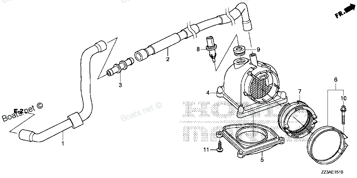
12357-ZZ3-000 TUBE A, BREATHER Honda
BF60AK1 LRTA, BF60AK1 XRTA, BFP60AK1 LRTA, BFP60AK1 LRTB, BFP60AK1 XRTA
TUBE

Price: query
You can buy parts:
As an associate, we earn commssions on qualifying purchases through the links below

$9.32
26-04-2024
0.375[0.17] pounds
US: HONDA-KTMSOUTHGA
Honda 12357-ZZ3-000 Tube A, Breather; 12357ZZ3000 Made by Honda
Honda Genuine, OEM Honda Replacement Part || Honda replacement breather tube a, part number 12357-ZZ3-000
Honda Genuine, OEM Honda Replacement Part || Honda replacement breather tube a, part number 12357-ZZ3-000
Number on catalog scheme: 1
Compatible models:
Honda entire parts catalog list:
Information:
1. Remove bolt (1) that holds suction bell (3) to the oil pan plate. Bend the locks away from bolts (2). Remove bolts (2) that hold the suction tube to the oil pump. Remove the gasket from between the suction tube flange and the oil pump. 2. Remove two bolts (5) that hold the scavenge tube manifold (6) to the oil pump. Remove manifold (6) from tube (4). Check O-ring seals on tube (4). Make a replacement of the seals if necessary. Remove bolts (7) and remove the oil pump.Install Oil Pump
1. Put oil pump (1) in position under the cylinder block and install the bolts that hold it. 2. Install a new gasket between the oil pump and the scavenge tube manifold. Install manifold on tube. Install bolts (2) that hold manifold to oil pump.3. Put suction tube (3) in position on the oil pump. Make sure there is a new gasket between the flange on the suction tube and the oil pump.4. Install the bolts that hold the suction tube to the oil pump. Bend the locks against the bolts. Install the bolt that holds the bracket on the suction bell to the oil pan plate.end by:a) install oil panDisassemble Oil Pump
start by:a) remove oil pump 1. Remove idler gear (2). Remove bearing from gear with tooling (B).2. Remove suction bell (1).3. Remove the bolt and the washer from the oil pump drive gear. 4. Remove the drive gear from the shaft with tooling (A).5. Remove the key from the pump shaft.6. Remove bolts (3) from the pump body. 7. Remove body (8), two gears (7), keys and spacer (4) from the pump.8. Remove two shafts (5) and the gears.9. Remove bolts (6), the cover and the pressure relief valve from the body. 10. Remove the bearings from the oil pump body assembly and the scavenge pump body assembly with tooling (C).Assemble Oil Pump
1. Install the bearings in the scavenge pump body assembly with tooling (A) as follows: a) Put bearings (1) in position on the inside of the scavenge pump body assembly with the chamfer on the bearing as shown. Install the bearing until it is .060 in. (1.52 mm) below the inside machined surface of the scavenge pump body assembly. Make sure the joints in the bearings are at an angle of 30° 15° from the center line through the bores in the scavenge pump body assembly as shown.2. Install the bearings in oil pump body assembly with tooling (A) as follows: a) Put bearing (2) in position on the inside of the oil pump body assembly with the chamfer on the bearings as shown. Install the bearings until they are even with the outside surface of the oil pump body assembly.3. Check the condition of the relief valve. Check the condition and specifications for all the parts of the oil pump before it is assembled. See OIL PUMP in SPECIFICATIONS.4. Put clean engine oil on all of the parts of the oil pump. 5. Install pressure relief valve (3), cover (4) and bolt (5) in the oil pump body assembly. 6. Install gears and shafts (6) in the oil pump body assembly.7. Install spacer (7) and the two keys in shafts (6). 8. Install two gears and scavenge pump body assembly (8).9. Install key (9), drive gear (11), the washer and bolt (10). Tighten the bolt to a torque of 32 5 lb. ft. (43 7 N m).10. Install the bearing in the idler gear with tooling (B) until it is even with the outside surface of the gear.11. Install the idler gear.
The oil pump must turn freely by hand after it is assembled.
end by: a) install oil pump
Parts tube Honda:
37202-ZW5-U01

37202-ZW5-U01 TUBE, SPEEDOMETER (4X7X8000) (Honda Code 7702202).
BF115A3 LA, BF115A3 LCA, BF115A3 XA, BF115A3 XCA, BF115A4 LA, BF115A4 LCA, BF115A4 XA, BF115A4 XCA, BF115A5 LA, BF115A5 LCA, BF115A5 XA, BF115A5 XCA, BF115A6 LA, BF115A6 LCA, BF115A6 XA, BF115A6 XCA, BF115AK0 LA, BF115AK0 XA, BF115DK1 LA, BF115DK1 XA
91408-ZJ1-810
91408-ZJ1-810 TUBE, CORD (30MM) (Honda Code 4210498).
BF25D4 LHTA, BF25D4 LRGA, BF25D4 LRTA, BF25D4 SHGA, BF25D4 SRGA, BF25D4 SRTA, BF25D5 LHTA, BF25D5 LRGA, BF25D5 LRTA, BF25D5 SHGA, BF25D5 SRGA, BF25D5 SRTA, BF25D6 LHTA, BF25D6 LRGA, BF25D6 LRTA, BF25D6 SHGA, BF25D6 SRGA, BF25D6 SRTA, BF25DK0 LRGA, BF
17701-ZY9-E03

17701-ZY9-E03 TUBE, FUEL LONG (7.3X2000)
BF115DK1 LA, BF115DK1 XA, BF115DK1 XCA, BF135AK2 LA, BF135AK2 XA, BF135AK2 XCA, BF150AK2 LA, BF150AK2 XA, BF150AK2 XCA, BF15DK2 LHA, BF15DK2 LHSA, BF15DK2 LHTA, BF15DK2 LRTA, BF15DK2 SHA, BF15DK2 SHSA, BF15DK2 SHTA, BF15DK3 LHA, BF15DK3 LHSA, BF15DK3
16199-ZZ3-000
16199-ZZ3-000 TUBE E, AIR VENT
BF60AK1 LRTA, BF60AK1 XRTA, BFP60AK1 LRTA, BFP60AK1 LRTB, BFP60AK1 XRTA
16748-ZZ3-000
16748-ZZ3-000 TUBE, PRESSURE REGULATOR CONTROL
BF60AK1 LRTA, BF60AK1 XRTA, BFP60AK1 LRTA, BFP60AK1 LRTB, BFP60AK1 XRTA
16850-ZZ3-A01
16865-ZZ3-A00
16866-ZZ3-A00