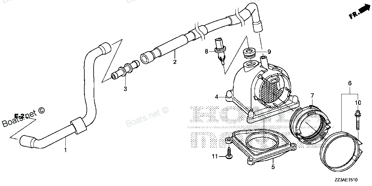
12359-ZZ3-000 TUBE B, BREATHER Honda
BF60AK1 LRTA, BF60AK1 XRTA, BFP60AK1 LRTA, BFP60AK1 LRTB, BFP60AK1 XRTA
TUBE

Price: query
You can buy parts:
As an associate, we earn commssions on qualifying purchases through the links below

$30.68
26-05-2024
0.5[0.23] Pounds
US: PowerToolReplacement
Honda 12359-ZZ3-000 Tube B, Breather; 12359ZZ3000 Made by Honda
Honda Genuine, OEM Honda Replacement Part || Honda replacement breather tube b, part number 12359-ZZ3-000
Honda Genuine, OEM Honda Replacement Part || Honda replacement breather tube b, part number 12359-ZZ3-000
Number on catalog scheme: 2
Compatible models:
Honda entire parts catalog list:
Information:
start by:a) remove oil pumpb) remove oil pan plate 1. Remove the No. 1, 3, 5 and 7 main bearing caps (1). Remove the crankshaft thrust bearing from the No. 7 main bearing.2. Remove the lower half of the main bearing from the main bearing caps.
If the crankshaft is turned in the wrong direction, the tab on bearing will be pushed between the crankshaft and bearing area in block which can cause damage to the block or crankshaft.
3. Install tool (A) in the oil hole in the crankshaft journal and remove the upper half of the main bearing as the crankshaft is turned and the main bearing is moved out of the cylinder block. Install the main bearings dry when the clearance checks are made. Put clean engine oil on the main bearings for final assembly.
Make sure the upper and lower halves of the main bearings are installed so the bearing tabs fit into the notch in cylinder block and the main bearing caps.
4. Install new lower half of main bearings (2) in the main bearing caps. Use tool (A) and install the upper half of the main bearings in the cylinder block.5. Put clean oil on the thrust bearing and install a new thrust bearing for the No. 7 main bearing. Install the thrust bearing with the identification "BLOCK SIDE" toward the cylinder block and the tabs on the thrust bearings in the machined area in the cylinder block. The tabs will not let the thrust bearing be installed backward. When the bearing clearance is checked and the engine is in a vertical position, such as in the vehicle, the crankshaft will have to be lifted up and held against the upper halves of the main bearings to get a correct measurement with the Plastigage. The Plastigage will not hold the weight of the crankshaft and give a correct indication. If the engine is in a horizontal position, it is not necessary to hold the crankshaft up. Do not turn the crankshaft when the Plastigage is in position to check clearances.6. Check the main bearing clearances with Plastigage (B) as follows: a) Put a piece of Plastigage (B) on the surface of the lower half of the main bearing.
Make sure the part number on the main bearing cap is toward the front of the engine and the number on the main bearing cap is the same as the number on the cylinder block on the left side of each main bearing cap.
Do not turn the crankshaft when Plastigage (B) is in position. b) Install main bearing caps (1) for No. 1, 3, 5 and 7 main bearings. Put clean engine oil on the bolt threads and the face of the washers and install the bolts. Tighten the bolts to a torque of 30 3 lb.ft. (40 4 N m).
Do not use an impact wrench to tighten the bolts the additional 90°.
c) Put a mark on each bolt and main bearing cap, then tighten the bolts 90° more.d) Remove the main bearing caps for No. 1, 3, 5 and 7 main bearings. Remove Plastigage (B) and measure the width of the Plastigage. The main bearing clearance must be .0030 to .0065 in. (0.076 to 0.165 mm). Maximum permissible clearance with used bearings is .010 in. (0.25 mm).7. Install main bearing caps (1) and tighten the bolts as in Steps 6b and 6c.8. Remove No. 2, 4 and 6 main bearing caps. Do Steps 2, 3, 4, 6 and 7 for the No. 2, 4 and 6 main bearings. 9. Check the crankshaft end play with tooling (C). The end play is controlled by the thrust bearings on the No. 7 main bearing. End play with new bearings is .0025 to .0145 in. (0.064 to 0.368 mm). The maximum permissible end play with used bearings is .025 in. (0.64 mm).end play:a) install oil pan plateb) install oil pump
Parts tube Honda:
37202-ZW5-U01

37202-ZW5-U01 TUBE, SPEEDOMETER (4X7X8000) (Honda Code 7702202).
BF115A3 LA, BF115A3 LCA, BF115A3 XA, BF115A3 XCA, BF115A4 LA, BF115A4 LCA, BF115A4 XA, BF115A4 XCA, BF115A5 LA, BF115A5 LCA, BF115A5 XA, BF115A5 XCA, BF115A6 LA, BF115A6 LCA, BF115A6 XA, BF115A6 XCA, BF115AK0 LA, BF115AK0 XA, BF115DK1 LA, BF115DK1 XA
91408-ZJ1-810
91408-ZJ1-810 TUBE, CORD (30MM) (Honda Code 4210498).
BF25D4 LHTA, BF25D4 LRGA, BF25D4 LRTA, BF25D4 SHGA, BF25D4 SRGA, BF25D4 SRTA, BF25D5 LHTA, BF25D5 LRGA, BF25D5 LRTA, BF25D5 SHGA, BF25D5 SRGA, BF25D5 SRTA, BF25D6 LHTA, BF25D6 LRGA, BF25D6 LRTA, BF25D6 SHGA, BF25D6 SRGA, BF25D6 SRTA, BF25DK0 LRGA, BF
17701-ZY9-E03

17701-ZY9-E03 TUBE, FUEL LONG (7.3X2000)
BF115DK1 LA, BF115DK1 XA, BF115DK1 XCA, BF135AK2 LA, BF135AK2 XA, BF135AK2 XCA, BF150AK2 LA, BF150AK2 XA, BF150AK2 XCA, BF15DK2 LHA, BF15DK2 LHSA, BF15DK2 LHTA, BF15DK2 LRTA, BF15DK2 SHA, BF15DK2 SHSA, BF15DK2 SHTA, BF15DK3 LHA, BF15DK3 LHSA, BF15DK3
12357-ZZ3-000
12357-ZZ3-000 TUBE A, BREATHER
BF60AK1 LRTA, BF60AK1 XRTA, BFP60AK1 LRTA, BFP60AK1 LRTB, BFP60AK1 XRTA
16199-ZZ3-000
16199-ZZ3-000 TUBE E, AIR VENT
BF60AK1 LRTA, BF60AK1 XRTA, BFP60AK1 LRTA, BFP60AK1 LRTB, BFP60AK1 XRTA
16748-ZZ3-000
16748-ZZ3-000 TUBE, PRESSURE REGULATOR CONTROL
BF60AK1 LRTA, BF60AK1 XRTA, BFP60AK1 LRTA, BFP60AK1 LRTB, BFP60AK1 XRTA
16850-ZZ3-A01
16865-ZZ3-A00