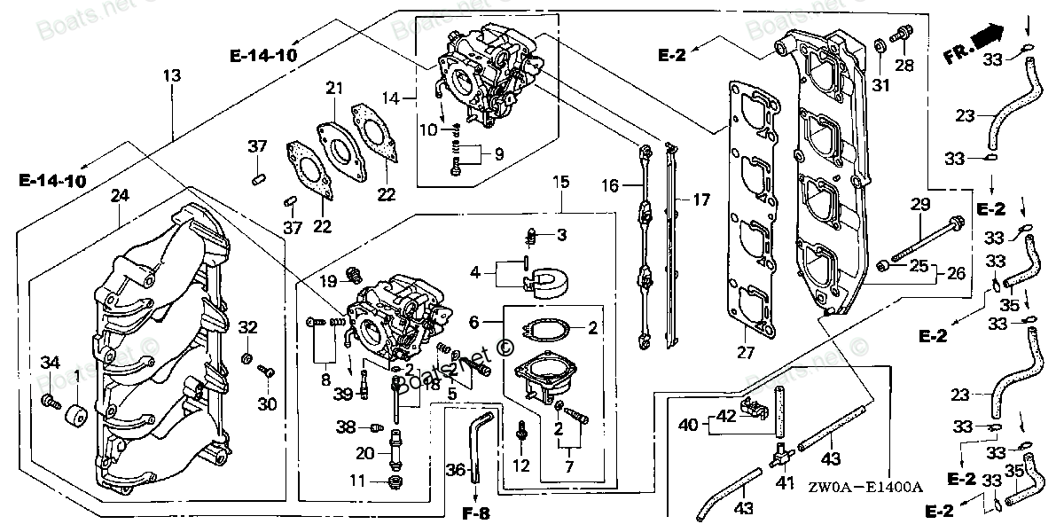
17387-ZW1-000 TUBE ASSY., DRAIN (Honda Code 7977903). Honda
BF75A5 LHTA, BF75A5 LRTA, BF75A5 XRTA, BF75A6 LHTA, BF75A6 LRTA, BF75A6 XRTA, BF90A5 JHTA, BF90A5 JRTA, BF90A5 LHTA, BF90A5 LRTA, BF90A5 XRTA, BF90A6 JHTA, BF90A6 JRTA, BF90A6 LHTA, BF90A6 LRTA, BF90A6 XRTA
TUBE
. Honda parts")
Price: query
Rating:
You can buy parts:
As an associate, we earn commssions on qualifying purchases through the links below

$13.36
15-09-2024
0.25[0.11] Pounds
US: HONDA-KTMSOUTHGA
Honda 17387-ZW1-000 Tube Assy. Drain
Honda HomeImprovement
Honda HomeImprovement
Number on catalog scheme: 40
Compatible models:
Honda entire parts catalog list:
- CARBURETOR » 17387-ZW1-000
- CARBURETOR » 17387-ZW1-000
- CARBURETOR » 17387-ZW1-000
- CARBURETOR » 17387-ZW1-000
- CARBURETOR » 17387-ZW1-000
- CARBURETOR » 17387-ZW1-000
- CARBURETOR » 17387-ZW1-000
- CARBURETOR » 17387-ZW1-000
- CARBURETOR » 17387-ZW1-000
- CARBURETOR » 17387-ZW1-000
- CARBURETOR » 17387-ZW1-000
- CARBURETOR » 17387-ZW1-000
- CARBURETOR » 17387-ZW1-000
- CARBURETOR » 17387-ZW1-000
- CARBURETOR » 17387-ZW1-000
- CARBURETOR » 17387-ZW1-000
Information:
1-1 Starter
The starter is an overhang type in which the pinion sliding surfaces are not exposed to the outside.Major components include: the motor that develops a high torque required to get the engine started; overrunning clutch that transmits torque and prevents the starter from overrunning; magnetic switch that brings the pinion into mesh with the ring gear, while turning on/off the load current to the motor; and, the reduction gear which boosts the armature torque. (1) Reduction Gear The end of the armature is a gear which is in mesh with the reduction gear.The armature torque is multiplied by about 3.6 with its speed reduced as they are transmitted to the pinion. (2) Overrunning Clutch A roller-type overrunning clutch is used.Rollers are housed in the wedge-shaped grooves formed by the outer and inner races (sleeve) and pressed by springs.When the starter is started, the roller is pressed towards the narrower side of the groove, functioning as a key to transmit rotation of the outer race to the pinion. No torque is transmitted, however, from the pinion (as it is turned by the engine), as the roller compresses the spring moving toward the wider side of groove and releasing the key action.(3) Operation While the starter switch is ON, current flows from the terminal "SW" of the starter relay to the terminal "L" and closes the contact P2.When the contact P2 closes, current from the battery flows from the terminal "S" of the magnetic switch to the pull-in coil (P) and holding coil (H). Furthermore, the current that has decreased flows from the terminal "M" to the motor section.The plunger, attracted by the magnetic flux of the pull-in coil and holding coil, closes the contact P1 and simultaneously pushes out the pinion turning slowly on weak current. When the pinion comes into complete mesh with the ring gear, the contact P1 closes and the large current of the battery directly flows to the motor section to turn the pinion powerfully.In this condition, no current flows to the pull-in coil. The plunger is retained by the holding coil alone. When the starter switch is placed to OFF, current to the holding coil (H) is interrupted. The plunger is returned to its original position by the return spring and the contact P1 opens so that current to the motor section is interrupted.The moment the starter switch is opened, the battery current flows from the terminal "B" to the pull-in coil (P) and holding coil (H). Since the coils are wound in opposite direction to each other, the magnetic fluxes cancel each other so that the return spring can move the plunger back to its original position.1-2 Alternator <Idle-speed Efficient Type>
The alternator with a built-in IC regulator (abbreviated to the built-in alternator) is used.The alternator consists of the IC regulator and brush holder accommodated in the rear bracket. Features of the Built-in Alternator(1) For better voltage buildup especially at idle speeds, the alternator is provided with the R terminal independent from the L terminal (charge lamp circuit) as the initial excitation circuit.(2) The three diodes (diode trio) built into the alternator apply the field current directly to the field coil, eliminating voltage drop caused by the starter switch and wiring.(3) The P terminal is for detecting the safety relay frequency. OperationWhen the starter switch is turned ON, base current flows from the battery to power transistor to turn it ON, allowing the current to flow through the field coil to turn on the charge lamp. As the engine starts with the alternator generating power, the base current is supplied by the alternator itself.The field current also flows from the diode trio to energize the rotor.At the time the charge lamp goes off, since the output voltage from the B terminal becomes the same as that from the L terminal. As the voltage developed by the alternator builds up, the zener diode Dz conducts providing base current for the transistor Trl to turn it ON.As a result, the base current of the power transistor is shorted to Trl, which turns OFF the power transistor. This means that there is no field current flow, dropping the voltage generated by the alternator.When the zener diode Dz is shut off with a voltage drop, the base current flows to the power transistor to turn it ON. As a result, the field current again starts flowing, increasing the generated voltage.These IC regulator operations repeat to regulate the alternator voltage.1-3 Vacuum Pump
The vacuum pump is of a rotary type with movable vanes. The rotor with three movable vanes turns in the housing of a cylindrical shape. The housing is mounted on the rear bracket of the alternator with the rotor spline-coupled into the alternator shaft.The rotor and housing are eccentric. The air drawn in through the suction port is gradually compressed and discharged from the deliver port. Oil is also drawn in through the oil filler port to provide sealing, lubricating, and cooling functions for the housing, and discharged from the deliver port with the compressed air to the oil pan. The check valve prevents the engine oil and compressed air from flowing back to the vacuum tank when the engine is stationary. 1-4 Safety Relay
The alternator rpm is detected and when it exceeds the reference level, the safety relay prevents the starter from operating even if its switch is accidentally turned on during engine revolution.Operation (1) When the starter switch is set to ON, current flow from the starter relay to terminal "S" and to terminal "E" of the safety relay, closing contact P1. The charge lamp also illuminates if provided.(2) As the starter runs and the engine starts running, pulses of frequency 1/10th of the alternator speed appear at terminal "P" of the alternator. The charge lamp goes out.(3) When the pulse frequency at terminal "P" exceeds the specified value, continuity between terminals "S" and "E" is lost. Then, the starter does not operate even if the starter switch is set to ON while the
Parts tube Honda:
17701-ZV5-000

17701-ZV5-000 TUBE, FUEL (7.5X2000) (Honda Code 3702305).
BF115A1 LA, BF115A1 LCA, BF115A1 XA, BF115A1 XCA, BF115A2 LA, BF115A2 LCA, BF115A2 XA, BF115A2 XCA, BF115A3 LA, BF115A3 LCA, BF115A3 XA, BF115A3 XCA, BF115A4 LA, BF115A4 LCA, BF115A4 XA, BF115A4 XCA, BF115A5 LA, BF115A5 LCA, BF115A5 XA, BF115A5 XCA,
17702-ZV4-000
17702-ZV4-000 TUBE, FUEL SHORT (Honda Code 2795557).
BF115A1 LA, BF115A1 LCA, BF115A1 XA, BF115A1 XCA, BF115A2 LA, BF115A2 LCA, BF115A2 XA, BF115A2 XCA, BF115A3 LA, BF115A3 LCA, BF115A3 XA, BF115A3 XCA, BF115A4 LA, BF115A4 LCA, BF115A4 XA, BF115A4 XCA, BF115A5 LA, BF115A5 LCA, BF115A5 XA, BF115A5 XCA,
16851-ZW1-000

16851-ZW1-000 TUBE A, FUEL (Honda Code 4897914).
BF75A1 LHTA, BF75A1 LRTA, BF75A1 XRTA, BF75A2 LHTA, BF75A2 LRTA, BF75A2 XRTA, BF75A3 LHTA, BF75A3 LRTA, BF75A3 XRTA, BF75A4 LHTA, BF75A4 LRTA, BF75A4 XRTA, BF75A5 LHTA, BF75A5 LRTA, BF75A5 XRTA, BF75A6 LHTA, BF75A6 LRTA, BF75A6 XRTA, BF75AT LHTA, BF7
15422-ZW1-000
15422-ZW1-000 TUBE, OIL (Honda Code 4897658).
BF75A1 LHTA, BF75A1 LRTA, BF75A1 XRTA, BF75A2 LHTA, BF75A2 LRTA, BF75A2 XRTA, BF75A3 LHTA, BF75A3 LRTA, BF75A3 XRTA, BF75A4 LHTA, BF75A4 LRTA, BF75A4 XRTA, BF75A5 LHTA, BF75A5 LRTA, BF75A5 XRTA, BF75A6 LHTA, BF75A6 LRTA, BF75A6 XRTA, BF75AT LHTA, BF7
16861-ZW1-000
16861-ZW1-000 TUBE B, FUEL (Honda Code 4897922).
BF75A1 LHTA, BF75A1 LRTA, BF75A1 XRTA, BF75A2 LHTA, BF75A2 LRTA, BF75A2 XRTA, BF75A3 LHTA, BF75A3 LRTA, BF75A3 XRTA, BF75A4 LHTA, BF75A4 LRTA, BF75A4 XRTA, BF75A5 LHTA, BF75A5 LRTA, BF75A5 XRTA, BF75A6 LHTA, BF75A6 LRTA, BF75A6 XRTA, BF75AT LHTA, BF7
36104-ZW1-003
36104-ZW1-003 TUBE, SPIRAL (12X14.6) (Honda Code 4899696).
BF115A1 LA, BF115A1 LCA, BF115A1 XA, BF115A1 XCA, BF115A2 LA, BF115A2 LCA, BF115A2 XA, BF115A2 XCA, BF115A3 LA, BF115A3 LCA, BF115A3 XA, BF115A3 XCA, BF115A4 LA, BF115A4 LCA, BF115A4 XA, BF115A4 XCA, BF115A5 LA, BF115A5 LCA, BF115A5 XA, BF115A5 XCA,
37202-ZW5-U01
37202-ZW5-U01 TUBE, SPEEDOMETER (4X7X8000) (Honda Code 7702202).
BF115A3 LA, BF115A3 LCA, BF115A3 XA, BF115A3 XCA, BF115A4 LA, BF115A4 LCA, BF115A4 XA, BF115A4 XCA, BF115A5 LA, BF115A5 LCA, BF115A5 XA, BF115A5 XCA, BF115A6 LA, BF115A6 LCA, BF115A6 XA, BF115A6 XCA, BF115AK0 LA, BF115AK0 XA, BF115DK1 LA, BF115DK1 XA
16881-ZW1-L00
16881-ZW1-L00 TUBE D, FUEL (Honda Code 6552749).
BF75A1 LHTA, BF75A1 LRTA, BF75A1 XRTA, BF75A2 LHTA, BF75A2 LRTA, BF75A2 XRTA, BF75A3 LHTA, BF75A3 LRTA, BF75A3 XRTA, BF75A4 LHTA, BF75A4 LRTA, BF75A4 XRTA, BF75A5 LHTA, BF75A5 LRTA, BF75A5 XRTA, BF75A6 LHTA, BF75A6 LRTA, BF75A6 XRTA, BF90A1 JHTA, BF9