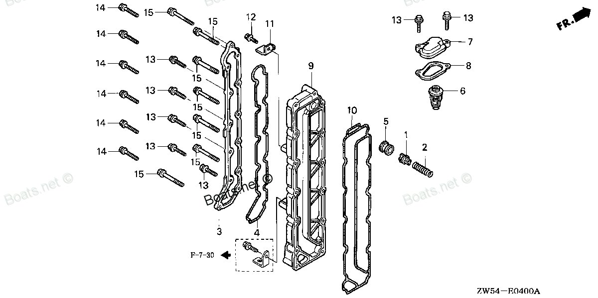
19291-ZW5-000 VALVE, RELIEF (Honda Code 5891387). Honda
BF115A1 LA, BF115A1 LCA, BF115A1 XA, BF115A1 XCA, BF115A2 LA, BF115A2 LCA, BF115A2 XA, BF115A2 XCA, BF115A3 LA, BF115A3 LCA, BF115A3 XA, BF115A3 XCA, BF115A4 LA, BF115A4 LCA, BF115A4 XA, BF115A4 XCA, BF115A5 LA, BF115A5 LCA, BF115A5 XA, BF115A5 XCA,
VALVE
. Honda parts")
Price: query
Rating:
You can buy parts:
As an associate, we earn commssions on qualifying purchases through the links below

$6.99
26-06-2024
0.25[0.11] pounds
US: HONDA-KTMSOUTHGA
Honda 19291-ZW5-000 Valve Relief
Honda Honda 19291-ZW5-000 Valve Relief
Honda Honda 19291-ZW5-000 Valve Relief
Number on catalog scheme: 1
Compatible models:
BF115A1 LA
BF115A1 LCA
BF115A1 XA
BF115A1 XCA
BF115A2 LA
BF115A2 LCA
BF115A2 XA
BF115A2 XCA
BF115A3 LA
BF115A3 LCA
BF115A3 XA
BF115A3 XCA
BF115A4 LA
BF115A4 LCA
BF115A4 XA
BF115A4 XCA
BF115A5 LA
BF115A5 LCA
BF115A5 XA
BF115A5 XCA
BF115A6 LA
BF115A6 LCA
BF115A6 XA
BF115A6 XCA
BF115AK0 LA
BF115AK0 XA
BF115AX LA
BF115AX LCA
BF115AX XA
BF115AX XCA
BF115AY LA
BF115AY LCA
BF115AY XA
BF115AY XCA
BF130A1 LA
BF130A1 LCA
BF130A1 XA
BF130A1 XCA
BF130A2 LA
BF130A2 LCA
BF130A2 XA
BF130A2 XCA
BF130A3 LA
BF130A3 LCA
BF130A3 XA
BF130A3 XCA
BF130A4 LA
BF130A4 LCA
BF130A4 XA
BF130A4 XCA
BF130AX LA
BF130AX LCA
BF130AX XA
BF130AX XCA
BF130AY LA
BF130AY LCA
BF130AY XA
BF130AY XCA
BF175AK1 LA
BF175AK1 XA
BF175AK1 XCA
BF175AK2 LA
BF175AK2 XA
BF175AK2 XCA
BF200A2 LA
BF200A2 XA
BF200A2 XCA
BF200A2 XXA
BF200A2 XXCA
BF200A3 LA
BF200A3 XA
BF200A3 XCA
BF200A3 XXA
BF200A3 XXCA
BF200A4 LA
BF200A4 XA
BF200A4 XCA
BF200A4 XXA
BF200A4 XXCA
BF200A5 LA
BF200A5 XA
BF200A5 XCA
BF200A5 XXA
BF200A5 XXCA
BF200A6 LA
BF200A6 XA
BF200A6 XCA
BF200A6 XXA
BF200A6 XXCA
BF200AK0 LA
BF200AK0 XA
BF200AK0 XCA
BF200AK1 LA
BF200AK1 XA
BF200AK1 XCA
BF200AK2 LA
BF200AK2 XA
BF200AK2 XCA
BF225A2 LA
BF225A2 XA
BF225A2 XCA
BF225A2 XXA
BF225A2 XXCA
BF225A3 LA
BF225A3 XA
BF225A3 XCA
BF225A3 XXA
BF225A3 XXCA
BF225A4 LA
BF225A4 XA
BF225A4 XCA
BF225A4 XXA
BF225A4 XXCA
BF225A5 LA
BF225A5 XA
BF225A5 XCA
BF225A5 XXA
BF225A5 XXCA
BF225A6 LA
BF225A6 XA
BF225A6 XCA
BF225A6 XXA
BF225A6 XXCA
BF225AK0 LA
BF225AK0 XA
BF225AK0 XCA
BF225AK0 XXA
BF225AK0 XXCA
BF225AK1 LA
BF225AK1 XA
BF225AK1 XCA
BF225AK1 XXA
BF225AK1 XXCA
BF225AK2 LA
BF225AK2 XA
BF225AK2 XCA
BF225AK2 XXA
BF225AK2 XXCA
BF250A LA
BF250A XA
BF250A XCA
BF250A XXA
BF250A XXCA
Honda
Honda entire parts catalog list:
- THERMOSTAT » 19291-ZW5-000
- THERMOSTAT » 19291-ZW5-000
- THERMOSTAT » 19291-ZW5-000
- THERMOSTAT » 19291-ZW5-000
- THERMOSTAT » 19291-ZW5-000
- THERMOSTAT » 19291-ZW5-000
- THERMOSTAT » 19291-ZW5-000
- THERMOSTAT » 19291-ZW5-000
- THERMOSTAT » 19291-ZW5-000
- THERMOSTAT » 19291-ZW5-000
- THERMOSTAT » 19291-ZW5-000
- THERMOSTAT » 19291-ZW5-000
- THERMOSTAT » 19291-ZW5-000
- THERMOSTAT » 19291-ZW5-000
- THERMOSTAT » 19291-ZW5-000
- THERMOSTAT » 19291-ZW5-000
- THERMOSTAT » 19291-ZW5-000
- THERMOSTAT » 19291-ZW5-000
- THERMOSTAT » 19291-ZW5-000
- THERMOSTAT » 19291-ZW5-000
- THERMOSTAT » 19291-ZW5-000
- THERMOSTAT » 19291-ZW5-000
- THERMOSTAT » 19291-ZW5-000
- THERMOSTAT » 19291-ZW5-000
- THERMOSTAT » 19291-ZW5-000
- THERMOSTAT » 19291-ZW5-000
- THERMOSTAT » 19291-ZW5-000
- THERMOSTAT » 19291-ZW5-000
- THERMOSTAT » 19291-ZW5-000
- THERMOSTAT » 19291-ZW5-000
- THERMOSTAT » 19291-ZW5-000
- THERMOSTAT » 19291-ZW5-000
- THERMOSTAT » 19291-ZW5-000
- THERMOSTAT » 19291-ZW5-000
- THERMOSTAT » 19291-ZW5-000
- THERMOSTAT » 19291-ZW5-000
- THERMOSTAT » 19291-ZW5-000
- THERMOSTAT » 19291-ZW5-000
- THERMOSTAT » 19291-ZW5-000
- THERMOSTAT » 19291-ZW5-000
- THERMOSTAT » 19291-ZW5-000
- THERMOSTAT » 19291-ZW5-000
- THERMOSTAT » 19291-ZW5-000
- THERMOSTAT » 19291-ZW5-000
- THERMOSTAT » 19291-ZW5-000
- THERMOSTAT » 19291-ZW5-000
- THERMOSTAT » 19291-ZW5-000
- THERMOSTAT » 19291-ZW5-000
- THERMOSTAT » 19291-ZW5-000
- THERMOSTAT » 19291-ZW5-000
- THERMOSTAT » 19291-ZW5-000
- THERMOSTAT » 19291-ZW5-000
- THERMOSTAT » 19291-ZW5-000
- THERMOSTAT » 19291-ZW5-000
- THERMOSTAT » 19291-ZW5-000
- THERMOSTAT » 19291-ZW5-000
- THERMOSTAT » 19291-ZW5-000
- THERMOSTAT » 19291-ZW5-000
- MOUNT CASE » 19291-ZW5-000
- MOUNT CASE » 19291-ZW5-000
- MOUNT CASE » 19291-ZW5-000
- MOUNT CASE » 19291-ZW5-000
- MOUNT CASE » 19291-ZW5-000
- MOUNT CASE » 19291-ZW5-000
- MOUNT CASE » 19291-ZW5-000
- MOUNT CASE » 19291-ZW5-000
- MOUNT CASE » 19291-ZW5-000
- MOUNT CASE » 19291-ZW5-000
- MOUNT CASE » 19291-ZW5-000
- MOUNT CASE » 19291-ZW5-000
- MOUNT CASE » 19291-ZW5-000
- MOUNT CASE » 19291-ZW5-000
- MOUNT CASE » 19291-ZW5-000
- MOUNT CASE » 19291-ZW5-000
- MOUNT CASE » 19291-ZW5-000
- MOUNT CASE » 19291-ZW5-000
- MOUNT CASE » 19291-ZW5-000
- MOUNT CASE » 19291-ZW5-000
- MOUNT CASE » 19291-ZW5-000
- MOUNT CASE » 19291-ZW5-000
- MOUNT CASE » 19291-ZW5-000
- MOUNT CASE » 19291-ZW5-000
- MOUNT CASE » 19291-ZW5-000
- MOUNT CASE » 19291-ZW5-000
- MOUNT CASE » 19291-ZW5-000
- MOUNT CASE » 19291-ZW5-000
- MOUNT CASE » 19291-ZW5-000
- MOUNT CASE » 19291-ZW5-000
- MOUNT CASE » 19291-ZW5-000
- MOUNT CASE » 19291-ZW5-000
- MOUNT CASE » 19291-ZW5-000
- MOUNT CASE » 19291-ZW5-000
- MOUNT CASE » 19291-ZW5-000
- MOUNT CASE » 19291-ZW5-000
- MOUNT CASE » 19291-ZW5-000
- MOUNT CASE » 19291-ZW5-000
- MOUNT CASE » 19291-ZW5-000
- MOUNT CASE » 19291-ZW5-000
- MOUNT CASE » 19291-ZW5-000
- MOUNT CASE » 19291-ZW5-000
- MOUNT CASE » 19291-ZW5-000
- MOUNT CASE » 19291-ZW5-000
- MOUNT CASE » 19291-ZW5-000
- MOUNT CASE » 19291-ZW5-000
- MOUNT CASE » 19291-ZW5-000
- MOUNT CASE » 19291-ZW5-000
- MOUNT CASE » 19291-ZW5-000
- MOUNT CASE » 19291-ZW5-000
- MOUNT CASE » 19291-ZW5-000
- MOUNT CASE » 19291-ZW5-000
- MOUNT CASE » 19291-ZW5-000
- MOUNT CASE » 19291-ZW5-000
- MOUNT CASE » 19291-ZW5-000
- MOUNT CASE » 19291-ZW5-000
- MOUNT CASE » 19291-ZW5-000
Information:
Table 1
Diagnostic Trouble Code for the Water-in-Fuel Sensor
J1939 Code Code Description Comments
97-3 Water In Fuel Indicator : Voltage Above Normal The ECM detects the following conditions:
An open circuit in the Water-In-Fuel (WIF) sensor circuit.
The warning lamp will stay on when the "indicator lamp self check" has been completed. The ECM will disable the function to detect water in fuel while the code is active. Water-in-Fuel Sensor OperationThe WIF sensor is a normally open sensor. During normal operation, there will be no signal sent from the WIF sensor to the ECM. If water is detected in the fuel, the sensor will send a signal to the ECM. If the signal remains constant for 5 seconds, a 97-15 diagnostic code will become active. If the signal remains constant for 30 minutes, a 97-16 diagnostic will become active. These diagnostic codes can also be caused by a short in the WIF sensor circuit.
Illustration 1 g06498535
Schematic diagram for the WIF sensor
Note: All connectors may not be shown. Refer to the Electrical Schematic for the application for details of any connectors between the WIF sensor connector and the ECM connectors.
Table 2
Troubleshooting Test Steps Values Results
1. Inspect Electrical Connectors and Wiring
A. Turn the keyswitch to the OFF position.
B. Thoroughly inspect the connector for the WIF sensor and any interface connectors between the WIF sensor and the ECM connectors. Refer to Troubleshooting, "Electrical Connectors - Inspect".
C. Perform a 45 N (10 lb) pull test on each of the wires in the WIF sensor connector and any interface connectors that are associated with the WIF sensor.
D. Check the harness for abrasions, for pinch points, and for corrosion.
Note: Do not disconnect the ECM connector at this stage. The ECM can only be disconnected and reconnected 10 times before damage to the harness connector may occur.
Loose connection or damaged wire
Result: There is a fault in a connector or the wiring.
Repair: Repair any faulty connectors or replace the wiring harness. Ensure that all the seals are properly in place and ensure that the connectors are correctly coupled.
Use the electronic service tool to clear all logged diagnostic codes and verify that the repair eliminates the fault.
Result: All connectors, pins, and sockets are correctly coupled and/or inserted. The harness is free of corrosion, abrasion, and pinch points.
Proceed to Test Step 2.
2. Check For Active Diagnostic Codes
A. Turn the keyswitch to the OFF position.
B. Connect the electronic service tool to the diagnostic connector.
C. Turn the keyswitch to the ON position. If the engine will start, then run the engine.
D. Wait for at least 1 minute.
E. Monitor the active diagnostic code screen on the electronic service tool. Check and record any active diagnostic codes.
Diagnostic codes
Result: There are no active diagnostic codes for the WIF sensor.
There may be an intermittent fault.
Repair: Refer to Troubleshooting, "Electrical Connectors - Inspect" to identify intermittent faults.
Result: A 97-15 or 97-16 diagnostic code is active.
Refer to Troubleshooting, "Fuel Contains Water" before continuing with this procedure.
Proceed to Test Step 3.
Result: A 97-3 diagnostic code is active.
Proceed to Test Step 3.
3. Check the Supply Voltage at the Sensor Connector
A. Turn the keyswitch to the OFF position.
B. Disconnect the WIF sensor connector.
C. Turn the keyswitch to the ON position.
D. Measure the voltage between the sensor supply and sensor return terminals on the harness connector for the WIF sensor.
E. Turn the keyswitch to the OFF position.
Between 11 V and 13 V for a 12 V system.
Between 22 V and 26 V for a 24 V system
Result: The voltage is not within the expected range. The fault is in the sensor supply wire or the return wire .
Repair: Repair the faulty sensor connector or replace the faulty harness.
Use the electronic service tool to clear all logged diagnostic codes and verify that the repair eliminates the fault.
Result: The voltage is within the expected range.
Reconnect the WIF sensor to the harness. Proceed to Test Step 4.
4. Check that the Diagnostic Code is Still Active
A. Turn the keyswitch to the OFF position.
B. Connect the electronic service tool to the diagnostic connector.
C. Turn the keyswitch to the ON position. Wait for at least 1 minute.
D. Monitor the active diagnostic code screen on the electronic service tool. Check and record any active diagnostic codes.
Diagnostic code
Result: A 97-3 diagnostic code is active.
Proceed to Test Step 5.
Result: A 97-15 diagnostic code is active.
Proceed to Test Step 8.
Result: No diagnostic code is active.
Return the unit to service.
5. Create a Short Circuit at the Sensor Connector
A.Turn the keyswitch to the ON position. Wait for at least 1 minute.
B. Disconnect the WIF sensor from the harness.
C. Fabricate a jumper wire that is 150 mm (6 inch) long.
D. Use the jumper to connect the sensor signal terminal to the sensor return terminal on the harness connector for the WIF sensor.
E. Monitor the active diagnostic code screen on the electronic service tool. Check and record any active diagnostic codes.
Open circuit
Result: A 97-3 diagnostic code was active before installing the jumper. A 97-15 code was active with the jumper installed. There is an open circuit in the WIF sensor.
Repair: Install a replacement sensor. Refer to Disassembly and Assembly, "Water Separator and Fuel Filter (Primary) - Remove and Install" for the correct procedure.
Use the electronic service tool to clear all logged diagnostic codes and verify that the repair eliminates the fault.
Result: There is still an active 97-3 diagnostic code with the jumper installed. The sensor is OK.
Proceed to Test Step 6.
6. Check the Wiring Between the WIF Sensor and the Interface Connector (if equipped) for an Open Circuit
Note: This step is only applicable if an interface connector is installed between the WIF sensor and the ECM. Refer to the Electrical Schematic for the application for more information. Proceed to Test Step 7 if no interface connector is installed.
A. Turn the keyswitch to the OFF position.
B. Disconnect the connector for the WIF sensor. Disconnect the interface connector between the WIF sensor and the ECM.
C. Use a suitable multimeter to measure the resistance between the sensor signal terminal on the WIF sensor harness connector and the sensor signal terminal on the
Parts valve Honda:
12372-879-000

12372-879-000 VALVE, BREATHER (Honda Code 0452151).
BF2AM SA, BF2AM SAB, BF2AW LA, BF2AW SA, BF2AW SAB, BF5A1 LA, BF5A1 SA, BF5A2 LA, BF5A2 SA, BF5A3 LA, BF5A3 SA, BF5A4 LA, BF5A4 SA, BF5A5 LA, BF5A5 SA, BF5A6 LA, BF5A6 SA, BF5AK0 LA, BF5AK0 SA, BF5AK2 LA, BF5AK2 SA, BF5AK3 LA, BF5AK3 SA, BF5AM LA, BF
15231-413-020

15231-413-020 VALVE, RELIEF (Honda Code 0690453).
BF25A1 LHA, BF25A1 LHSA, BF25A1 LRSA, BF25A1 SHA, BF25A1 SHSA, BF25A1 SRSA, BF25A1 XRSA, BF25A2 LHA, BF25A2 LHSA, BF25A2 LRSA, BF25A2 SHA, BF25A2 SHSA, BF25A2 SRSA, BF25A2 XRSA, BF25A3 LHA, BF25A3 LHSA, BF25A3 LRSA, BF25A3 SHA, BF25A3 SHSA, BF25A3 SR
14721-P0A-000

14721-P0A-000 VALVE, EX. (Honda Code 4327847).
BF115A1 LA, BF115A1 LCA, BF115A1 XA, BF115A1 XCA, BF115A2 LA, BF115A2 LCA, BF115A2 XA, BF115A2 XCA, BF115A3 LA, BF115A3 LCA, BF115A3 XA, BF115A3 XCA, BF115A4 LA, BF115A4 LCA, BF115A4 XA, BF115A4 XCA, BF115A5 LA, BF115A5 LCA, BF115A5 XA, BF115A5 XCA,
36550-ZW5-003
36550-ZW5-003 VALVE ASSY., ELECTRONIC AIR (Honda Code 5892351). CONTROL
BF115A1 LA, BF115A1 LCA, BF115A1 XA, BF115A1 XCA, BF115A2 LA, BF115A2 LCA, BF115A2 XA, BF115A2 XCA, BF115A3 LA, BF115A3 LCA, BF115A3 XA, BF115A3 XCA, BF115A4 LA, BF115A4 LCA, BF115A4 XA, BF115A4 XCA, BF115A5 LA, BF115A5 LCA, BF115A5 XA, BF115A5 XCA,
36145-PM4-004

36145-PM4-004 VALVE, CHECK (Honda Code 3427283).
BF175AK1 LA, BF175AK1 XA, BF175AK1 XCA, BF175AK2 LA, BF175AK2 XA, BF175AK2 XCA, BF200A2 LA, BF200A2 XA, BF200A2 XCA, BF200A2 XXA, BF200A2 XXCA, BF200A3 LA, BF200A3 XA, BF200A3 XCA, BF200A3 XXA, BF200A3 XXCA, BF200A4 LA, BF200A4 XA, BF200A4 XCA, BF200
36163-ZY3-003
36163-ZY3-003 VALVE ASSY., AIR BYPASS (Honda Code 6991954).
BF135A4 LA, BF135A4 XA, BF135A4 XCA, BF135A5 LA, BF135A5 XA, BF135A5 XCA, BF135A6 LA, BF135A6 XA, BF135A6 XCA, BF135AK0 LA, BF135AK0 XA, BF135AK0 XCA, BF135AK2 LA, BF135AK2 XA, BF135AK2 XCA, BF150A4 LA, BF150A4 XA, BF150A4 XCA, BF150A5 LA, BF150A5 XA
14711-PNA-000

14711-PNA-000 VALVE, IN.
BF115DK1 LA, BF115DK1 XA, BF115DK1 XCA, BF135A4 LA, BF135A4 XA, BF135A4 XCA, BF135A5 LA, BF135A5 XA, BF135A5 XCA, BF135A6 LA, BF135A6 XA, BF135A6 XCA, BF135AK0 LA, BF135AK0 XA, BF135AK0 XCA, BF135AK2 LA, BF135AK2 XA, BF135AK2 XCA, BF150A4 LA, BF150A4
14721-PRB-A00
14721-PRB-A00 VALVE, EX.
BF115DK1 LA, BF115DK1 XA, BF115DK1 XCA, BF135A4 LA, BF135A4 XA, BF135A4 XCA, BF135A5 LA, BF135A5 XA, BF135A5 XCA, BF135A6 LA, BF135A6 XA, BF135A6 XCA, BF135AK0 LA, BF135AK0 XA, BF135AK0 XCA, BF135AK2 LA, BF135AK2 XA, BF135AK2 XCA, BF150A4 LA, BF150A4