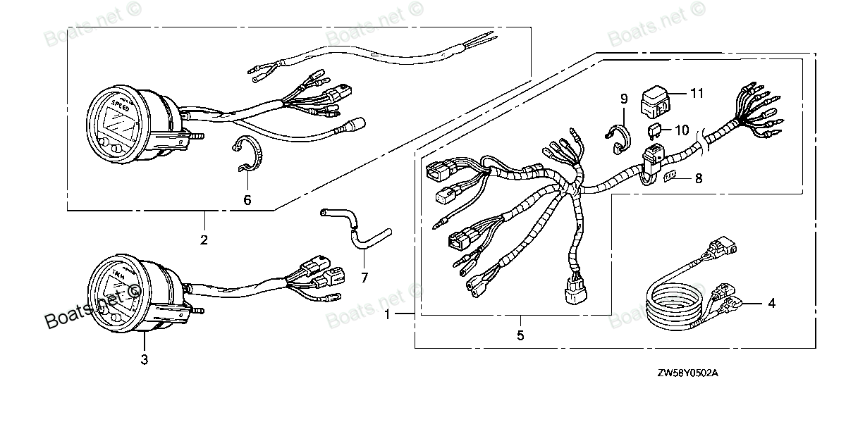
32185-ZY6-000 WIRE ASSY., INDICATOR (DIGITAL) Honda
BF115A4 LA, BF115A4 XA, BF115A5 LA, BF115A5 LCA, BF115A5 XA, BF115A5 XCA, BF115A6 LA, BF115A6 LCA, BF115A6 XA, BF115A6 XCA, BF115AK0 LA, BF115AK0 XA, BF130A4 LA, BF130A4 LCA, BF130A4 XA, BF130A4 XCA, BF135A4 LA, BF135A4 XA, BF135A4 XCA, BF135A5 LA, B
WIRE
 Honda parts")
Price: query
Rating:
You can buy parts:
As an associate, we earn commssions on qualifying purchases through the links below

$30.17
31-03-2024
0.25[0.11] Pounds
US: HONDA-KTMSOUTHGA
Honda 32185-ZY6-000 Wire Indicator
Honda Honda 32185-ZY6-000 Wire Indicator
Honda Honda 32185-ZY6-000 Wire Indicator
Number on catalog scheme: 4
Compatible models:
BF115A4 LA
BF115A4 XA
BF115A5 LA
BF115A5 LCA
BF115A5 XA
BF115A5 XCA
BF115A6 LA
BF115A6 LCA
BF115A6 XA
BF115A6 XCA
BF115AK0 LA
BF115AK0 XA
BF130A4 LA
BF130A4 LCA
BF130A4 XA
BF130A4 XCA
BF135A4 LA
BF135A4 XA
BF135A4 XCA
BF135A5 LA
BF135A5 XA
BF135A5 XCA
BF135A6 LA
BF135A6 XA
BF135A6 XCA
BF135AK0 LA
BF135AK0 XA
BF135AK0 XCA
BF150A4 LA
BF150A4 XA
BF150A4 XCA
BF150A5 LA
BF150A5 XA
BF150A5 XCA
BF150A6 LA
BF150A6 XA
BF150A6 XCA
BF150AK0 LA
BF150AK0 XA
BF150AK0 XCA
BF175AK1 LA
BF175AK1 XA
BF175AK1 XCA
BF200A4 LA
BF200A4 XA
BF200A4 XCA
BF200A4 XXA
BF200A4 XXCA
BF200A5 LA
BF200A5 XA
BF200A5 XCA
BF200A5 XXA
BF200A5 XXCA
BF200A6 LA
BF200A6 XA
BF200A6 XCA
BF200A6 XXA
BF200A6 XXCA
BF200AK0 LA
BF200AK0 XA
BF200AK0 XCA
BF200AK1 LA
BF200AK1 XA
BF200AK1 XCA
BF225A2 XCA
BF225A2 XXCA
BF225A4 LA
BF225A4 XA
BF225A4 XCA
BF225A4 XXA
BF225A4 XXCA
BF225A5 LA
BF225A5 XA
BF225A5 XCA
BF225A5 XXA
BF225A5 XXCA
BF225A6 LA
BF225A6 XA
BF225A6 XCA
BF225A6 XXA
BF225A6 XXCA
BF225AK0 LA
BF225AK0 XA
BF225AK0 XCA
BF225AK0 XXA
BF225AK0 XXCA
BF225AK1 LA
BF225AK1 XA
BF225AK1 XCA
BF225AK1 XXA
BF225AK1 XXCA
BF75DK0 LHTA
BF75DK0 LRTA
BF90DK0 LHTA
BF90DK0 LRTA
BF90DK0 XRTA
Honda
Honda entire parts catalog list:
- METER (DIGITAL) » 32185-ZY6-000
- METER (DIGITAL) » 32185-ZY6-000
- METER (DIGITAL) » 32185-ZY6-000
- METER (DIGITAL) » 32185-ZY6-000
- METER (DIGITAL) » 32185-ZY6-000
- METER (DIGITAL) » 32185-ZY6-000
- METER (DIGITAL) » 32185-ZY6-000
- METER (DIGITAL) » 32185-ZY6-000
- METER (DIGITAL) » 32185-ZY6-000
- METER (DIGITAL) » 32185-ZY6-000
- METER (DIGITAL) » 32185-ZY6-000
- METER (DIGITAL) » 32185-ZY6-000
- METER (DIGITAL) » 32185-ZY6-000
- METER (DIGITAL) » 32185-ZY6-000
- METER (DIGITAL) » 32185-ZY6-000
- METER (DIGITAL) » 32185-ZY6-000
- STARTER CABLE (1) » 32185-ZY6-000
- METER (3) » 32185-ZY6-000
- STARTER CABLE » 32185-ZY6-000
- STARTER CABLE (1) » 32185-ZY6-000
- METER (3) » 32185-ZY6-000
- STARTER CABLE » 32185-ZY6-000
- STARTER CABLE (1) » 32185-ZY6-000
- METER (3) » 32185-ZY6-000
- STARTER CABLE » 32185-ZY6-000
- STARTER CABLE » 32185-ZY6-000
- STARTER CABLE (1) » 32185-ZY6-000
- METER (3) » 32185-ZY6-000
- STARTER CABLE (1) » 32185-ZY6-000
- METER (3) » 32185-ZY6-000
- STARTER CABLE » 32185-ZY6-000
- STARTER CABLE (1) » 32185-ZY6-000
- METER (3) » 32185-ZY6-000
- STARTER CABLE » 32185-ZY6-000
- STARTER CABLE » 32185-ZY6-000
- STARTER CABLE (1) » 32185-ZY6-000
- METER (3) » 32185-ZY6-000
- STARTER CABLE (1) » 32185-ZY6-000
- METER (3) » 32185-ZY6-000
- STARTER CABLE » 32185-ZY6-000
- STARTER CABLE (1) » 32185-ZY6-000
- METER (3) » 32185-ZY6-000
- STARTER CABLE » 32185-ZY6-000
- STARTER CABLE (1) » 32185-ZY6-000
- METER (3) » 32185-ZY6-000
- STARTER CABLE » 32185-ZY6-000
- STARTER CABLE (1) » 32185-ZY6-000
- METER (3) » 32185-ZY6-000
- STARTER CABLE » 32185-ZY6-000
- STARTER CABLE (1) » 32185-ZY6-000
- METER (3) » 32185-ZY6-000
- STARTER CABLE » 32185-ZY6-000
- STARTER CABLE (1) » 32185-ZY6-000
- METER (3) » 32185-ZY6-000
- STARTER CABLE » 32185-ZY6-000
- METER (3) » 32185-ZY6-000
- STARTER CABLE » 32185-ZY6-000
- STARTER CABLE (1) » 32185-ZY6-000
- METER (3) » 32185-ZY6-000
- STARTER CABLE » 32185-ZY6-000
- STARTER CABLE (1) » 32185-ZY6-000
- STARTER CABLE (1) » 32185-ZY6-000
- METER (3) » 32185-ZY6-000
- STARTER CABLE » 32185-ZY6-000
- STARTER CABLE (1) » 32185-ZY6-000
- METER (3) » 32185-ZY6-000
- STARTER CABLE » 32185-ZY6-000
- STARTER CABLE (1) » 32185-ZY6-000
- METER (3) » 32185-ZY6-000
- STARTER CABLE » 32185-ZY6-000
- STARTER CABLE (1) » 32185-ZY6-000
- METER (3) » 32185-ZY6-000
- STARTER CABLE » 32185-ZY6-000
- STARTER CABLE (1) » 32185-ZY6-000
- METER (3) » 32185-ZY6-000
- STARTER CABLE » 32185-ZY6-000
- STARTER CABLE (1) » 32185-ZY6-000
- METER (3) » 32185-ZY6-000
- STARTER CABLE » 32185-ZY6-000
- STARTER CABLE (1) » 32185-ZY6-000
- METER (3) » 32185-ZY6-000
- STARTER CABLE » 32185-ZY6-000
- STARTER CABLE (1) » 32185-ZY6-000
- METER (3) » 32185-ZY6-000
- STARTER CABLE » 32185-ZY6-000
- METER (3) » 32185-ZY6-000
- STARTER CABLE » 32185-ZY6-000
- STARTER CABLE (1) » 32185-ZY6-000
- METER (1) » 32185-ZY6-000
- STARTER CABLE » 32185-ZY6-000
- STARTER CABLE » 32185-ZY6-000
- METER (1) » 32185-ZY6-000
- METER (1) » 32185-ZY6-000
- STARTER CABLE » 32185-ZY6-000
- METER (2) » 32185-ZY6-000
- STARTER CABLE » 32185-ZY6-000
- STARTER CABLE » 32185-ZY6-000
- METER (2) » 32185-ZY6-000
- METER (2) » 32185-ZY6-000
- STARTER CABLE » 32185-ZY6-000
- METER (2) » 32185-ZY6-000
- STARTER CABLE » 32185-ZY6-000
- STARTER CABLE » 32185-ZY6-000
- METER (2) » 32185-ZY6-000
- METER (2) » 32185-ZY6-000
- METER (2) » 32185-ZY6-000
- METER (2) » 32185-ZY6-000
- METER (2) » 32185-ZY6-000
- METER (2) » 32185-ZY6-000
- METER (1) » 32185-ZY6-000
- METER (1) » 32185-ZY6-000
- METER (1) » 32185-ZY6-000
- METER (1) » 32185-ZY6-000
- METER (1) » 32185-ZY6-000
- METER (1) » 32185-ZY6-000
Information:
Probable Causes
Wiring to the electronic unit injectors
Electronic unit injectors
Engine software and ECMRecommended Actions
Note: The procedures have been listed in order of probability. Complete the procedures in order.
Electrical Shock Hazard. The electronic unit injectors use DC voltage. The ECM sends this voltage to the electronic unit injectors. Do not come in contact with the harness connector for the electronic unit injectors while the engine is operating. Failure to follow this instruction could result in personal injury or death.
Table 2
Troubleshooting Test Steps Values Results
1. Diagnostic Codes
A. Download the Product Status Report (PSR) with Histograms before performing any troubleshooting or clearing any diagnostic codes.
Note: The downloaded information will be required by the Dealer Solutions Network (DSN) if troubleshooting assistance is needed.
B. Use the electronic service tool to check for active or logged diagnostic codes.
Diagnostic codes
Result: A diagnostic code is not active or logged.
Return the unit to service.
Result: A 190–10 diagnostic code is active or logged.
Proceed to Test Step 2.
2. Inspect Electrical Connectors and Wiring
A. Turn the keyswitch to the OFF position. A strong electrical shock hazard is present if the keyswitch is not turned OFF.
B: Thoroughly inspect the connectors at the cylinder head. Refer to Troubleshooting, Electrical Connectors - Inspect for details.
C. Perform a 30 N (6.7 lb) pull test on each of the wires in the ECM connector that are associated with the injector solenoids.
D. Check the harness and wiring for abrasions and for pinch points from the injectors to the ECM.
Loose connection or damaged wire
Result: There is a fault in the connector or the wiring.
Repair: Repair any faulty connectors or replace the wiring harness. Ensure that all the seals are properly in place and ensure that the connectors are correctly coupled.
Use the electronic service tool to clear all logged diagnostic codes and verify that the repair eliminates the fault.
Result: All connectors, pins, and sockets are correctly coupled and/or inserted. The harness is free of corrosion, abrasion, and pinch points.
Proceed to Test Step 3.
3. Use the "Injector Solenoid Test"
A. Start the engine.
B. Allow the engine to warm up to the normal operating temperature.
C. Stop the engine.
D. Turn the keyswitch to the ON position.
E. Access the "Injector Solenoid Test" in the electronic service tool by accessing the following screens:
• Diagnostics
• Diagnostic Tests
• Injector Solenoid Test
F. Activate the test.
Note: Do not confuse the "Injector Solenoid Test" with the "Cylinder Cutout Test". The "Cylinder Cutout Test" is used to shut off fuel to a specific cylinder while the engine is running. The "Injector Solenoid Test" is used to actuate the injector solenoids while the engine is not running.
"OK", "OPEN", or "SHORT"
Result: All cylinders indicate "OK".
There is not an electrical fault with the injectors.
Proceed to Test Step 4.
Result: "OPEN" or "SHORT" is indicated on any injector.
Note the cylinders that indicate "OPEN" or "SHORT".
Refer to Troubleshooting, Injector Solenoid - Test to diagnose the cause of the injector circuit fault.
4. Electronic Unit Injectors
A. Use the electronic service tool to perform the automatic "Cylinder Cutout Test". Refer to Troubleshooting, Service Tool Features for more information on the "Cylinder Cutout Test".
Electronic unit injectors
Result: A faulty cylinder is indicated.
Repair: Remove any faulty electronic unit injectors. Refer to Disassembly and Assembly, Electronic Unit Injector - Remove.
Install new electronic unit injectors. Refer to Disassembly and Assembly, Electronic Unit Injector - Install.
Repeat the automatic "Cylinder Cutout Test". If the fault is still present, remove the replacement electronic unit injector and install the original electronic unit injector. Refer to Disassembly and Assembly, Electronic Unit Injector - Remove and Disassembly and Assembly, Electronic Unit Injector - Install. Proceed to Test Step 5.
If the fault is cleared, return the unit to service.
Result: All injectors are OK.
Proceed to Test Step 5.
5. Engine Software and Electronic Control Module (ECM)
A. Make sure that the latest flash file for the application is installed in the engine ECM.
B. Ensure that the ECM has been powered down after the ECM flash file has been updated.
Software updated
Result The 190–10 does not recur after the software has been updated.
Return the unit to service.
Result The 190–10 code is still present after the software has been updated.
Proceed to Test Step 6.
6. Create an Electronic Service Tool Snapshot
A. Select "Snapshot Viewer" on the electronic service tool, using menus: Information -> Snapshot -> Viewer
B. Select the diagnostic code and then click "View Graph".
C. Select the following parameter and then click OK.
Engine Speed
D. Select Save to "File to save" a Snapshot File (*.xml). This file will contain all the data in the snapshot and not only the data shown on the graph.
Note: The downloaded information will be required by the Dealer Solutions Network (DSN) if diagnostic assistance is needed.
Snapshot saved
Result: The electronic service tool snapshot was successfully saved.
Contact the DSN.
Result: The electronic service tool snapshot was not successfully saved.
Contact the DSN for guidance.
Parts wire Honda:
32193-ZY3-000

32193-ZY3-000 WIRE, SWITCH (Honda Code 6991699).
BF200A2 LA, BF200A2 XA, BF200A2 XCA, BF200A2 XXA, BF200A2 XXCA, BF200A3 LA, BF200A3 XA, BF200A3 XCA, BF200A3 XXA, BF200A3 XXCA, BF200A4 LA, BF200A4 XA, BF200A4 XCA, BF200A4 XXA, BF200A4 XXCA, BF200A5 LA, BF200A5 XA, BF200A5 XCA, BF200A5 XXA, BF200A5
63237-ZY9-000
63237-ZY9-000 WIRE, FASTENER
BF40DK2 LHA, BF40DK2 LRTA, BF50DK2 LRTA, BF50DK2 XRTA, BF60AK1 LRTA, BF60AK1 XRTA, BF75DK0 LHTA, BF75DK0 LRTA, BF75DK2 LRTA, BF90DK0 LHTA, BF90DK0 LRTA, BF90DK0 XRTA, BF90DK2 LRTA, BF90DK2 XRTA, BFP60AK1 LRTA, BFP60AK1 LRTB, BFP60AK1 XRTA
32185-ZZ5-600
32185-ZZ5-600 WIRE ASSY., INDICATOR (20FT)
BF115DK1 LA, BF115DK1 XA, BF115DK1 XCA, BF135AK0 LA, BF135AK0 XA, BF135AK0 XCA, BF135AK2 LA, BF135AK2 XA, BF135AK2 XCA, BF150AK0 LA, BF150AK0 XA, BF150AK0 XCA, BF150AK2 LA, BF150AK2 XA, BF150AK2 XCA, BF175AK1 LA, BF175AK1 XA, BF175AK1 XCA, BF175AK2 L
32185-ZZ5-700
32185-ZZ5-700 WIRE ASSY., INDICATOR (25FT)
BF115DK1 LA, BF115DK1 XA, BF115DK1 XCA, BF135AK0 LA, BF135AK0 XA, BF135AK0 XCA, BF135AK2 LA, BF135AK2 XA, BF135AK2 XCA, BF150AK0 LA, BF150AK0 XA, BF150AK0 XCA, BF150AK2 LA, BF150AK2 XA, BF150AK2 XCA, BF175AK1 LA, BF175AK1 XA, BF175AK1 XCA, BF175AK2 L
32185-ZZ5-800
32185-ZZ5-800 WIRE ASSY., INDICATOR (30FT)
BF115DK1 LA, BF115DK1 XA, BF115DK1 XCA, BF135AK0 LA, BF135AK0 XA, BF135AK0 XCA, BF135AK2 LA, BF135AK2 XA, BF135AK2 XCA, BF150AK0 LA, BF150AK0 XA, BF150AK0 XCA, BF150AK2 LA, BF150AK2 XA, BF150AK2 XCA, BF175AK1 LA, BF175AK1 XA, BF175AK1 XCA, BF175AK2 L
32100-ZZ0-A00
32100-ZY5-050
32100-ZY5-050 WIRE HARNESS ASSY., MAIN
BF135AK0 LA, BF135AK0 XA, BF135AK0 XCA, BF135AK2 LA, BF135AK2 XA, BF135AK2 XCA
32100-ZY6-050
32100-ZY6-050 WIRE HARNESS ASSY., MAIN
BF150AK0 LA, BF150AK0 XA, BF150AK0 XCA, BF150AK2 LA, BF150AK2 XA, BF150AK2 XCA