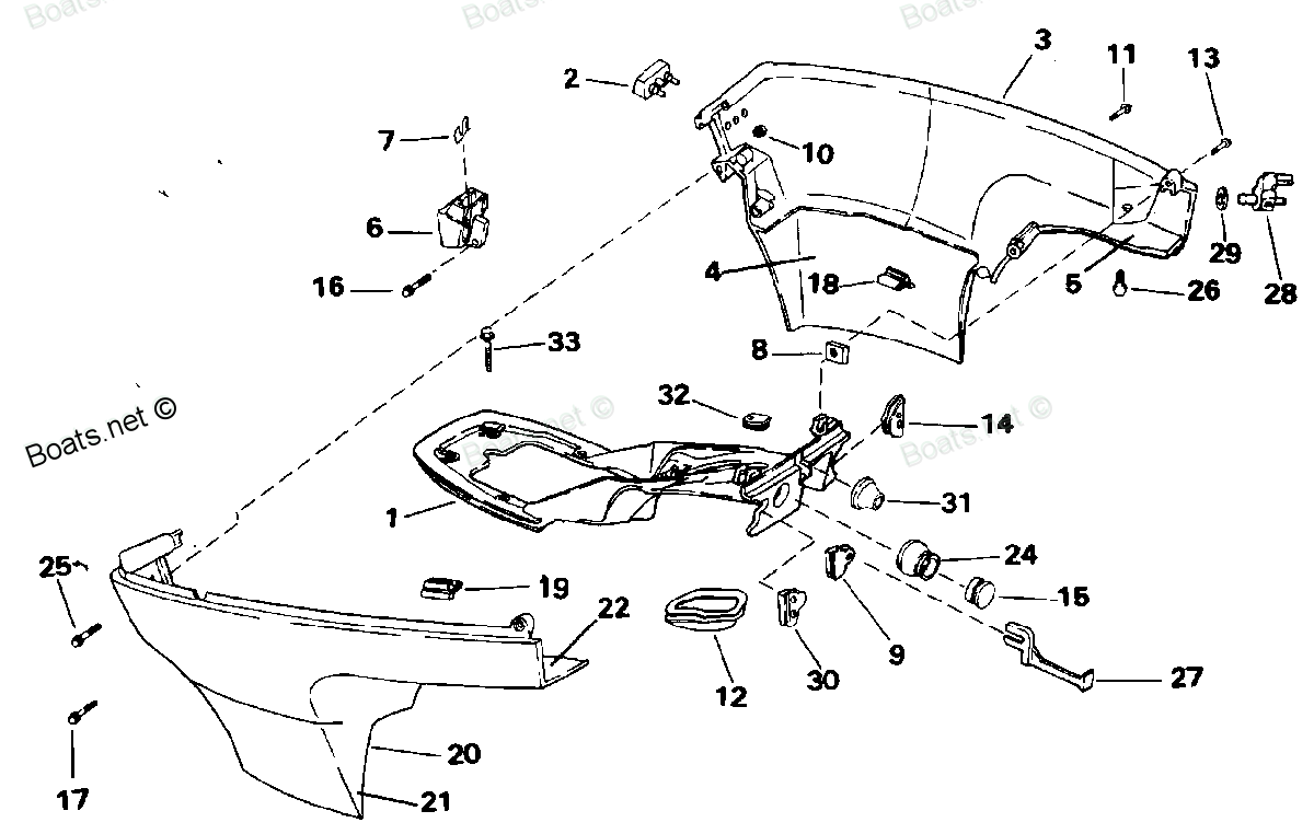
0336116 BUMPER, Cover JOHNSON
J10EERB, J10EETM, J15EERE, J15EETB, J6REIA, J6RENM, J6RERE, J6RETB, J8REIA, J8RENM, J8RERE, J8RETB
BUMPER

Price: query
Rating:
Number on catalog scheme: 2
Compatible models:
BRP JOHNSON entire parts catalog list:
- LOWER ENGINE COVER » 0336116
J15EERE, J15ELERE, J15RELERE, J15RERE, J15RLERE 1994
J15EETB, J15ELETB, J15RELETB, J15RETB, J15RLETB 1993
J6REIA, J6RLEIA, J6SLEIA 1991
J6RENM, J6RLENM, J6SLENM 1992
J6RERE, J6RLERE, J6SLERE 1994
J6RETB, J6RLETB, J6SLETB 1993
J8REIA, J8RLEIA, J8SRLEIA 1991
J8RENM, J8RLENM, J8SRLENM 1992
J8RERE, J8RLERE, J8SRLERE 1994
J8RETB, J8RLETB, J8SRLETB 1993
Information:
2. Remove water temperature gauge line (1) from the engine.3. Disconnect inlet oil line (2) and the two outlet lines (5) from the pump.4. Disconnect indicator line (3) for the oil pressure gauge.5. Disconnect all wires from starter (6) and solenoid (4). Put identification on each wire for correct installation.6. Disconnect the wire for the glow plugs. 7. Disconnect control linkage (7) for the governor.8. Disconnect fuel line (8).9. Disconnect the wires from the alternator.10. Remove bolts (9) from the right and left sides, that hold the front mounts for the engine to the frame. 11. Fasten a hoist and remove bolts (10) that hold the transmission to the flywheel housing. 12. Remove the engine. The weight is approximately 1000 lb. (450 kg).Install Engine (910)
1. Fasten a hoist and put the engine into position in the frame. 2. Put the engine in alignment with transmission (1) and install the bolts that hold the transmission to the flywheel housing.3. Install the bolts in the front engine mounts.4. Connect the wires to the alternator.5. Connect the fuel line.6. Connect the control linkage for the governor. 7. Connect wire (2) for the glow plugs.8. Connect the wires to the starter and solenoid.9. Connect indicator line (3) for the oil pressure gauge.10. Connect the lines to the hydraulic pump.11. Install the water temperature gauge line on the engine.12. Fill the hydraulic tank to the correct level.13. Turn the fuel valve on bottom of fuel tank to the "ON" position.end by:a) install air cleaner housingb) install mufflerc) install radiator and guard assemblyRemove Engine (D3 Or 931)
start by:a) remove radiator and guard assemblyb) remove mufflerc) remove air cleaner housing1. Remove the oil from the hydraulic tank and turn the fuel valve on the tank to the "OFF" position. 2. Remove pin (2) and disconnect linkage (1) from the governor control.3. Remove oil filter (3). 4. Disconnect line (6) for the air cleaner gauge. Disconnect wire (7) for glow plugs. Remove sending unit (8) for the water temperature.5. Disconnect all the wires from the starter and alternator. Put identification on the wires for correct installation. 6. Remove the hose clamp and disconnect two oil lines (9) from the hydraulic pump.7. Disconnect indicator line (10) for the oil pressure gauge. 8. Remove floor plates (11) from the platform of the machine.9. Remove the bottom guard for the transmission with a floor jack. Weight is 100 lb. (45 kg). 10. Disconnect fuel line (12). Put blocks or a floor jack under the front of the transmission.11. Remove bolts (13) that hold the flywheel housing to the transmission.12. Remove the cable from the flywheel housing that is used as a ground cable. 13. Remove bolts (14) from the right and left sides, that hold the front mounts for the engine to the frame. 14. Fasten a hoist to the lifting brackets and remove the engine. Weight is approximately 1000 lb. (450 kg).Install Engine (D3 or 931)
1. Fasten a hoist to the engine. Put the engine into position on the transmission and the engine mounts. 2. Install bolts (2) that hold the transmission to the flywheel housing.3. Connect line (1) for the fuel supply.4. Install the two bolts that hold the engine mounts to the frame.5. Connect all the wires to the starter and alternator. 6. Install oil lines (3) and (4) to the hydraulic pump and install the clamp.7. Install the oil pressure line to the engine.8. Install line (7) for the water temperature gauge. 9. Install line (5) for the air cleaner indicator.10. Connect wire (6) for the glow plugs. 11. Connect linkage (8) for the governor control.12. Install oil filter (9) for the engine.13. Install the floor plates.14. Fill the hydraulic tank to the correct level.15. Turn the fuel valve on bottom of the fuel tank to the "ON" position.end by:a) install air cleaner housingb) install mufflerc) install radiator and guard assembly