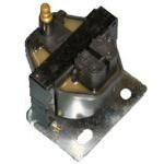
811639T COIL Mercruiser
4111021L1, 4111021TS, 4111021UT, 4111021UU, 411102KN2, 41510P1UE, 4231017L1, 4542067LS, 4652027LE, 4652027M1, 4652227MW
COIL

Price: query
Rating:
You can buy parts:
As an associate, we earn commssions on qualifying purchases through the links below

$26.59
26-03-2023
0.3[0.14] Pounds
-: -
CDI Electronics E13-0012 Pickup Coil Sensor - Mercruiser, Volvo
Pickup Coil Sensor for inboard ignitions || Fits Mercruiser and Volvo engines || Replaces 18-5108, 3854001, 72130, 802465, 811639, 811639T, 850489, 986642, E13-0012 || Constructed from high quality materials
Pickup Coil Sensor for inboard ignitions || Fits Mercruiser and Volvo engines || Replaces 18-5108, 3854001, 72130, 802465, 811639, 811639T, 850489, 986642, E13-0012 || Constructed from high quality materials

$59.99
27-06-2021
-: -
RECMAR Distributor Pick Up Sensor for Delco EST Ignition RO: 3854001 811639T 18-5108
GM 4 Cylinder, V6 & V8 Engines With Delco HEI Ignition || Mercruiser 811639T 811639 802465 850489 Volvo/OMC 3854001 OMC 986642
GM 4 Cylinder, V6 & V8 Engines With Delco HEI Ignition || Mercruiser 811639T 811639 802465 850489 Volvo/OMC 3854001 OMC 986642

$38.99
02-08-2023
1.0[0.45] Pounds
-: -
Distributor Pick-Up Coil
Quicksilver - Mercruiser 811639T, 710-811639T
Quicksilver - Mercruiser 811639T, 710-811639T
Number on catalog scheme: 6

Compatible models:
Mercruiser entire parts catalog list:
- EST IGNITION COMPONENTS » 811639T
- DISTRIBUTOR AND IGNITION COMPONENTS » 811639T
- DISTRIBUTOR AND IGNITION COMPONENTS » 811639T
- DISTRIBUTOR AND IGNITION COMPONENTS » 811639T
- EST IGNITION COMPONENTS » 811639T
- DISTRIBUTOR AND IGNITION COMPONENTS » 811639T
- DISTRIBUTOR(S-N-0L012009 - 0L359999) » 811639T
- DISTRIBUTOR AND IGNITION COMPONENTS » 811639T
- DISTRIBUTOR AND IGNITION COMPONENTS » 811639T
- DISTRIBUTOR AND IGNITION COMPONENTS » 811639T
- DISTRIBUTOR AND IGNITION COMPONENTS » 811639T
Information:
Table 1
Required Tools
Tool Part Number Part Description Qty
A(1) 9U-6198 Crankshaft Turning Tool 1
A(2) 9U-7336 Housing 1
5P-7305 Engine Turning Tool 1
B 8T-3052 Degree Wheel 1
(1) The Crankshaft Turning Tool is used on the front pulley.
(2) This Tool is used in the aperture for the electric starting motor.Note: Either Tooling (A) can be used. Use the Tooling that is most suitable.
Keep all parts clean from contaminants.Contaminants may cause rapid wear and shortened component life.
Discard all used Connecting Rod fasteners.
Inspect the pins of the crankshaft for damage. If the crankshaft is damaged, replace the crankshaft. Refer to Disassembly and Assembly, "Crankshaft - Remove" and Disassembly and Assembly, "Crankshaft - Install" for the correct procedure. Ensure that the bearing shells are clean and free from wear and damage. If necessary, replace the bearing shells.
Illustration 1 g02437999
Install upper bearing shell (5) into connecting rod (3). Ensure that the locating tab for the upper bearing shell is correctly seated in the slot in the connecting rod. Note: The ends of the upper bearing shell must be centered in the connecting rod. The ends of the upper bearing shell must be equally positioned in relation to the mating faces of the connecting rod.
Lubricate upper bearing shell (5) with clean engine oil.
Use Tooling (A) to rotate the crankshaft until the crankshaft pin is at the bottom dead center position.
Carefully pull connecting rod (3) against the crankshaft pin. Note: Do not allow the connecting rod to contact the piston cooling jet.
Clean connecting rod cap (2). Install lower bearing shell (4) into connecting rod cap (2). Ensure that the locating tab for the lower bearing shell is correctly seated in the slot in the connecting rod cap.
Lubricate the pin of the crankshaft and lubricate lower bearing shell (4) with clean engine oil.
Illustration 2 g02437998
Install connecting rod cap (2) to connecting rod (3). Note: Ensure that etched Number (X) on connecting rod cap (2) matches etched Number (X) on connecting rod (3). Ensure the correct orientation of the connecting rod cap. The locating tab for the upper bearing shell and the lower bearing shell should be on the same side.Note: Do not reuse the old connecting rod bolts in order to secure the connecting rod cap.
Install new bolts (1) to the connecting rod. Tighten the bolts evenly to a torque of 40 N m (30 lb ft).
Turn the bolts through an additional 120 degrees in a clockwise direction. Use Tooling (B) to achieve the correct final torque.
Ensure that the installed connecting rod assembly has tactile side play. Rotate the crankshaft in order to ensure that there is no binding.
Repeat Step 2 through Step 11 for the remaining connecting rod bearings. Note: If all connecting rod bearings require replacement, the procedure can be carried out on two cylinders at the same time. The procedure can be carried out on the following pairs of cylinders. 1 with 4 and 2 with 3. Ensure that both pairs of the connecting rod bearings are installed before changing from one pair of cylinders to another pair of cylinders. Refer to Disassembly and Assembly, "Connecting Rod Bearings - Install" for the correct procedure.
If the glow plugs were removed, install the glow plugs. Ref to Disassembly and Assembly, "Glow Plugs - Remove and Install" for the correct procedure. End By:
If the engine is equipped with a balancer, install the balancer. Refer to Disassembly and Assembly, "Balancer - Install" for the correct procedure.
If the engine is not equipped with a balancer, install the engine oil pump. Refer to Disassembly and Assembly, "Engine Oil Pump - Install" for the correct procedure.
Parts coil Mercruiser:
805570A 2

805570A 2 COIL KIT
02602347, 02608427, 257B021JS, 4211015L1, 4211025RS, 4211025TS, 4211025TT, 4211025US, 4211025UU, 4231017L1, 4332087N1, 4350100KS, 443B1003S, 443B100JS, 443HC00JT, 4441027LE, 444106LPS, 44541101S, 4454110GE, 4454110JT, 45021102S, 457B100KS, 4M11025LS,
811639

811639 COIL
4111021L1, 4262C01JT, 430B00001, 430L000JS, 4350104JS, 4350104KS, 4350111HS, 4350118JS, 4350118KS, 4441027LE, 444106AM1, 4454118JT, 4502111FE, 457B101JS, 457B101KS, 457B111GS, 457L101JS, 474L111JS, 474L118JS, 474L118JT, 4M31027LS
817378

817378 COIL, Ignition
4111021L1, 4111021TS, 411102KN2, 4231017L1, 4542067LS, 4652027LE, 4652027M1, 4652227MW
898253T27