13613-98100 Bolt Suzuki
DT15 MLE, DT15C, DT15ELD, DT15ELE, DT15ELF, DT15ELG, DT15ELH, DT15ELJ, DT15ESD, DT15ESE, DT15ESF, DT15ESG, DT15ESH, DT15ESJ, DT15MLD, DT15MLF, DT15MLG, DT15MLH, DT15MLJ, DT15MSD, DT15MSE, DT15MSF, DT15MSG, DT15MSH, DT15MSJ, DT16LT, DT16LT, DT16LT, DT
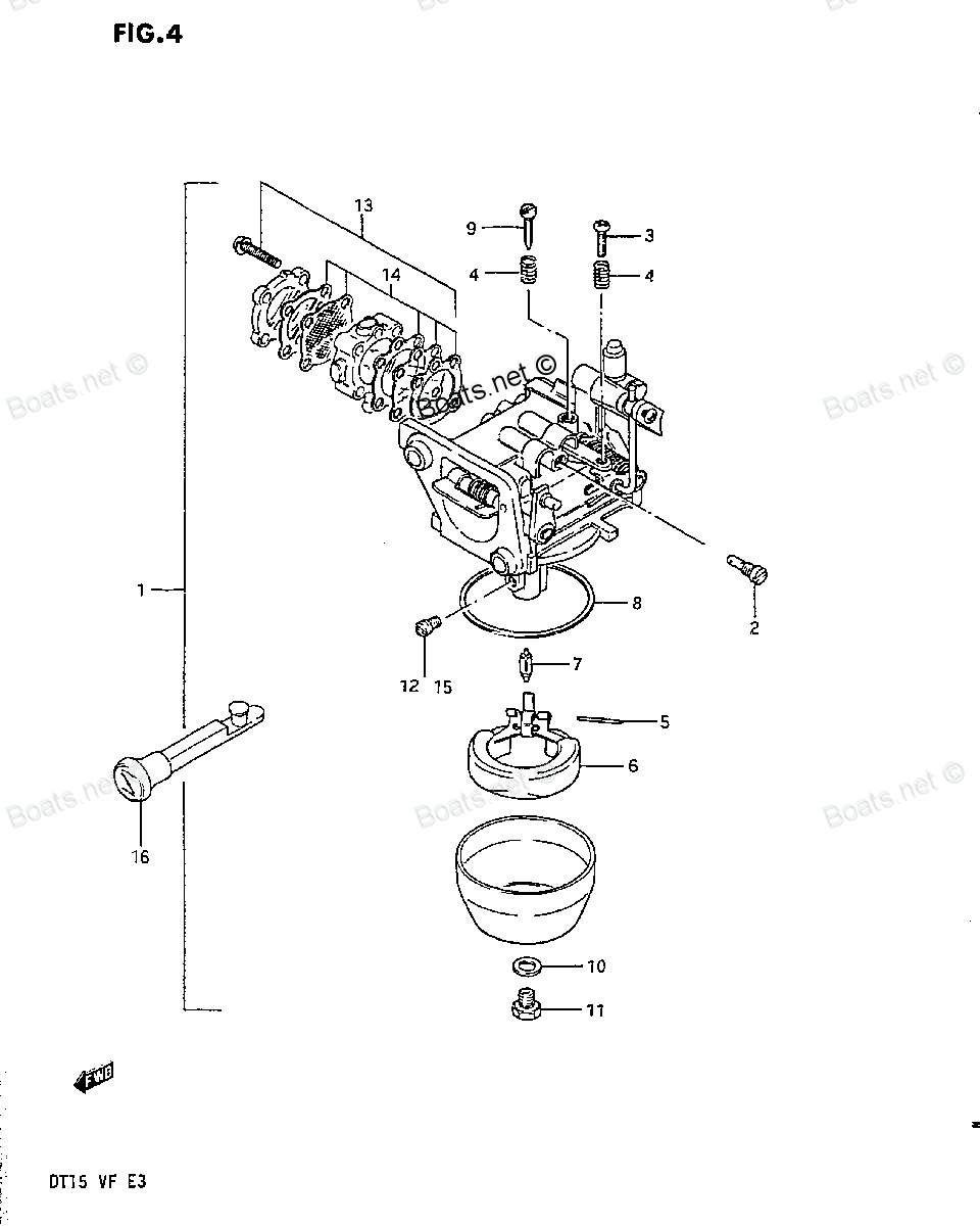
Bolt

Price: query
Rating:
Number on catalog scheme: 11
Compatible models:
DT15 MLE
DT15C
DT15ELD
DT15ELE
DT15ELF
DT15ELG
DT15ELH
DT15ELJ
DT15ESD
DT15ESE
DT15ESF
DT15ESG
DT15ESH
DT15ESJ
DT15MLD
DT15MLF
DT15MLG
DT15MLH
DT15MLJ
DT15MSD
DT15MSE
DT15MSF
DT15MSG
DT15MSH
DT15MSJ
DT16LT
DT16ST
DT8CENK
DT8CENL
DT8CLJ
DT8CLK
DT8CLL
DT8CLM
DT8CNK
DT8CNL
DT8CSJ
DT8CSL
DT8CSM
DT8LD
DT8LE
DT8LF
DT8LG
DT8LH
DT8LT
DT8LX
DT8LZ
DT8MCLN
DT8MCLP
DT8MCLS
DT8MCLT
DT8MCLV
DT8MCSN
DT8MCSP
DT8MCSR
DT8MCSS
DT8MCST
DT8MCSV
DT8MSLR
DT8SCK
DT8SD
DT8SE
DT8SF
DT8SG
DT8SH
DT8ST
DT8SX
DT8SZ
DT9.9 CELK
DT9.9CELJ
DT9.9CELL
DT9.9CELM
DT9.9CELN
DT9.9CELP
DT9.9CELR
DT9.9CELS
DT9.9CELT
DT9.9CENK
DT9.9CESJ
DT9.9CESK
DT9.9CESL
DT9.9CESM
DT9.9CESN
DT9.9CESP
DT9.9CESR
DT9.9CESS
DT9.9CEST
DT9.9CNELP
DT9.9CNELR
DT9.9CNELS
DT9.9CNELT
DT9.9CNEXP
DT9.9CNEXR
DT9.9CNEXS
DT9.9CNEXT
DT9.9CNEXV
DT9.9CNJ
DT9.9CNK
DT9.9CNL
DT9.9CNLN
DT9.9ELD
DT9.9ELE
DT9.9ELF
DT9.9ELG
DT9.9ELH
DT9.9ESD
DT9.9ESE
DT9.9ESF
DT9.9ESG
DT9.9ESH
DT9.9LT
DT9.9LX
DT9.9LZ
DT9.9MCLJ
DT9.9MCLK
DT9.9MCLL
DT9.9MCLM
DT9.9MCLN
DT9.9MCLP
DT9.9MCLR
DT9.9MCLS
DT9.9MCLT
DT9.9MCLV
DT9.9MCNLR
DT9.9MCNLT
DT9.9MCNLV
DT9.9MCSJ
DT9.9MCSK
DT9.9MCSL
DT9.9MCSM
DT9.9MCSN
DT9.9MCSP
DT9.9MCSR
DT9.9MCSS
DT9.9MCST
DT9.9MCSV
DT9.9MLD
DT9.9MLE
DT9.9MLF
DT9.9MLG
DT9.9MLH
DT9.9MSD
DT9.9MSE
DT9.9MSF
DT9.9MSG
DT9.9MSH
DT9.9ST
DT9.9SX
DT9.9SZ
Suzuki
Suzuki entire parts catalog list:
- Carburetor » 13613-98100
- CARBURETOR » 13613-98100
- Carburetor » 13613-98100
- Carburetor » 13613-98100
- Carburetor » 13613-98100
- Carburetor » 13613-98100
- Carburetor » 13613-98100
- Carburetor » 13613-98100
- Carburetor » 13613-98100
- Carburetor » 13613-98100
- Carburetor » 13613-98100
- Carburetor » 13613-98100
- Carburetor » 13613-98100
- Carburetor » 13613-98100
- Carburetor » 13613-98100
- Carburetor » 13613-98100
- Carburetor » 13613-98100
- Carburetor » 13613-98100
- Carburetor » 13613-98100
- Carburetor » 13613-98100
- Carburetor » 13613-98100
- Carburetor » 13613-98100
- Carburetor » 13613-98100
- Carburetor » 13613-98100
- Carburetor » 13613-98100
- Carburetor » 13613-98100
- Carburetor » 13613-98100
- Carburetor » 13613-98100
- Carburetor » 13613-98100
- Carburetor » 13613-98100
- Carburetor » 13613-98100
- CARBURETOR » 13613-98100
- CARBURETOR » 13613-98100
- CARBURETOR » 13613-98100
- CARBURETOR » 13613-98100
- CARBURETOR » 13613-98100
- CARBURETOR » 13613-98100
- CARBURETOR » 13613-98100
- CARBURETOR » 13613-98100
- CARBURETOR » 13613-98100
- CARBURETOR » 13613-98100
- CARBURETOR » 13613-98100
- Carburetor » 13613-98100
- Carburetor » 13613-98100
- Carburetor » 13613-98100
- Carburetor » 13613-98100
- Carburetor » 13613-98100
- Carburetor » 13613-98100
- Carburetor » 13613-98100
- Carburetor » 13613-98100
- CARBURETOR » 13613-98100
- CARBURETOR » 13613-98100
- CARBURETOR » 13613-98100
- CARBURETOR » 13613-98100
- CARBURETOR » 13613-98100
- CARBURETOR » 13613-98100
- CARBURETOR » 13613-98100
- CARBURETOR » 13613-98100
- CARBURETOR » 13613-98100
- CARBURETOR » 13613-98100
- CARBURETOR » 13613-98100
- CARBURETOR » 13613-98100
- CARBURETOR » 13613-98100
- Carburetor » 13613-98100
- Carburetor » 13613-98100
- Carburetor » 13613-98100
- Carburetor » 13613-98100
- Carburetor » 13613-98100
- Carburetor » 13613-98100
- Carburetor » 13613-98100
- Carburetor » 13613-98100
- CARBURETOR » 13613-98100
- CARBURETOR » 13613-98100
- CARBURETOR » 13613-98100
- CARBURETOR » 13613-98100
- CARBURETOR » 13613-98100
- CARBURETOR » 13613-98100
- CARBURETOR » 13613-98100
- CARBURETOR » 13613-98100
- CARBURETOR » 13613-98100
- CARBURETOR » 13613-98100
- CARBURETOR » 13613-98100
- CARBURETOR » 13613-98100
- CARBURETOR » 13613-98100
- CARBURETOR » 13613-98100
- CARBURETOR » 13613-98100
- CARBURETOR » 13613-98100
- CARBURETOR » 13613-98100
- CARBURETOR » 13613-98100
- CARBURETOR » 13613-98100
- CARBURETOR » 13613-98100
- CARBURETOR » 13613-98100
- CARBURETOR » 13613-98100
- CARBURETOR » 13613-98100
- CARBURETOR » 13613-98100
- CARBURETOR » 13613-98100
- CARBURETOR » 13613-98100
- CARBURETOR » 13613-98100
- CARBURETOR » 13613-98100
- CARBURETOR » 13613-98100
- CARBURETOR » 13613-98100
- CARBURETOR » 13613-98100
- CARBURETOR » 13613-98100
- Carburetor » 13613-98100
- Carburetor » 13613-98100
- Carburetor » 13613-98100
- Carburetor » 13613-98100
- Carburetor » 13613-98100
- Carburetor » 13613-98100
- Carburetor » 13613-98100
- Carburetor » 13613-98100
- Carburetor » 13613-98100
- Carburetor » 13613-98100
- Carburetor » 13613-98100
- Carburetor » 13613-98100
Information:
Only use antifreeze/coolant mixtures recommended in the Refill Capacities and Recommendations section of this manual. Failure to do so can cause engine damage.
Allow the engine to cool. Check the coolant level.
If freezing temperatures are expected, check the coolant for protection against freezing. The cooling system must be protected against freezing to the lowest expected outside temperature. Add the proper coolant/water mixture, if necessary.
Perform all required periodic maintenance on all driven equipment. Refer to the instructions that are provided by the OEM of the driven equipment.Aftertreatment Purge Cycle
Note: Air supply must remain active while the system purges.Under certain conditions the aftertreatment control system will run the DEF dosing system through a DEF purging cycle. This purge cycle will drain the AUS/DEF line between the dosing cabinet and the DEF injector. The purge cycle is designed to protect the AUS/DEF system, and to prevent the AUS/DEF from freezing. The purge cycle also protects engine exhaust hardware from AUS/DEF leaking from the DEF injector. The system will enter purge mode when the engine speed has dropped below a set threshold. The system will also enter a purge cycle if certain codes are logged during operation.During purge cycle, the AUS/DEF return valve on the AUS/DEF manifold will open and the dosing pump is turned off. The purge cycle will allow the air pressure in the line to force remaining AUS/DEF in the nozzle/line back to the tank inside the dosing cabinet. The purge cycle is a time-based event. The event should take less than 2 minutes.Note: If DC power is turned off before the purge cycle has been completed, the system will display a 3362-31: Aftertreatment #1 DEF Dosing Unit Input Lines upon start up.Shut down Procedure For the Oil Mist Detector
If a shutdown occurs due to excessive oil mist, use the following procedure.Note: Instructions from the Service Manual, "Disassembly and Assembly" module will be necessary in order to perform this procedure.
After the shutdown, inspect the control system for other alarm conditions. Compare the timing of the shutdown to the activation of the alarm. Ensure that the shutdown was initiated by the oil mist detector.
Inform the master engineer that the engine is unavailable.
Inspect the display of the oil mist detector in order to ensure that the shutdown is genuine. The green "Ready" indicator is OFF and the red "Alarm" indicator is FLASHING. Inspect the display for other faults.
After verifying the cause of the shutdown, shut off the air supply to the starting motor. This procedure will prevent accidental starting.
Open the cylinder pressure valves (Kiene valves) for all of the cylinders.
Guards must be in place prior to operating barring device motor.Remove all hand tools prior to operating barring device motor.
Do not use an impact wrench to operate the barring device. The use of an impact wrench will cause gear tooth failure.
Operate the prelube pump and the barring device. If the flywheel will rotate freely, rotate the engine for two complete revolutions (720 degrees). Lock the barring device.
Deactivate the prelube pump.
Flash fire may result in personal injury, if crankcase covers are removed within fifteen minutes after emergency shut down. Do not restart engine until cause for shutdown has been corrected.
After the engine has been shut down for 15 minutes, remove all of the crankcase covers. The oil mist detector monitors each section of the crankcase. First investigate the section with the fault condition.Note: Measure the temperatures quickly before the bearings can cool is important. This procedure will provide the most accurate indication of the operating temperatures of the bearings. Step 9 can be efficiently performed by two people: one person measures the temperatures, and one person records the temperatures.
Use a 123-6700 Laser Infrared Thermometer. Record all three temperatures for the small end bearing and for the large end bearing of each connecting rod. Record the temperatures for the front, the center, and the rear of each bearing.Note: Lower temperatures can be expected for a shutdown during partial load operation.
The temperature of any small end bearing should not exceed the average temperature of all of the small end bearings by more than 15 °C or 27°F. The temperature of any large end bearing should not exceed the average temperature of all of the large end bearings by more than 15 °C or 27°F.
The maximum temperature of any bearing after full load operation should not exceed 105 °C (221 °F).
Ensure that the large end bearings of the connecting rods can move freely. Normally, the rods can be moved slightly. Move the rods back and forth along the crankshaft journal.
If the following conditions occur, perform Steps 11.a and 11.b:
The temperatures are within the specifications that are listed in Steps 9.a and 9.b.
A closer visual inspection shows no damage to the following components: pistons, cylinder liners, piston pins, main bearings and gear trains.
Remove the oil filters. For instructions, see this Operation and Maintenance Manual, "Engine Oil Filter - Change" topic (Maintenance Section).
Cut the oil filters open with a utility knife. Inspect the pleats of the filter material for debris. The type of debris that is found will indicate components that require further inspection.
If the temperatures of the bearings exceed the specifications that are listed in Steps 9.a and 9.b, remove the components that are affected. Perform a full inspection of the components.
When the engine is in satisfactory condition, perform a complete inspection of the oil mist detector. For instructions, see the literature that is provided by the OEM of the detector.
Do not operate the engine starting motor until the barring group pinion gear is fully disengaged from the flywheel ring gear. Serious damage to the engine could result.
Start the engine according to this Operation and Maintenance Manual, "Engine Starting" topic (Operation Section). Operate the engine at low idle rpm for 10 minutes. If the oil mist detector causes another shutdown, repeat this entire procedure.
After the engine has operated with no problem for 10 minutes, stop the engine. Immediately remove all of the crankcase covers. Measure the temperatures of the connecting rod bearings. This procedure will verify the
Parts bolt Suzuki:
09100-06049
09100-06049 Bolt, Swivel
20ELB, 20ELC, 20ELN, 25ELB, 25ELC, 25ELN, DT14F, DT16LN, DT16LT, DT16LT, DT16LT, DT16SN, DT16ST, DT16ST, DT16ST, DT20ESB, DT20ESC, DT20ESN, DT20MLB, DT20MLC, DT20MLN, DT20MSB, DT20MSC, DT20MSN, DT25ESB, DT25ESC, DT25ESN, DT25MLB, DT25MLC, DT25MLN, DT
09100-10086
09100-10086 Bolt, Clamp Bracket
20ELB, 20ELC, 20ELN, 25ELB, 25ELC, 25ELN, 25ELT, 25ELX, DT14C, DT14D, DT14F, DT16LB, DT16LC, DT16LN, DT16LT, DT16LT, DT16LT, DT16SB, DT16SC, DT16SN, DT16ST, DT16ST, DT16ST, DT20ESB, DT20ESC, DT20ESN, DT20MLB, DT20MLC, DT20MLN, DT20MSB, DT20MSC, DT20M
01107-08208
01107-08208 Bolt
DT16LT, DT16ST, DT35ELT, DT35ELX, DT35ELZ, DT35EST, DT35ESX, DT35ESZ, DT35MLT, DT35MLX, DT35MLZ, DT35MST, DT35MSX, DT35MSZ, DT40ELT, DT40ELX, DT40ELZ, DT40EST, DT40ESX, DT40ESZ, DT40MLT, DT40MLX, DT40MLZ, DT40MSX, DT40MSZ, DT50, DT50, DT50ECLE, DT50E
01907-06168
01907-06168 Bolt
DT16LT, DT16LT, DT16LT, DT16ST, DT16ST, DT16ST, DT2T, DT2X, DT2Z, DT3.5LZ, DT3.5SZ, DT5LZ, DT5SZ, DT85ELT, DT85TCLT, DT85TCLX, DT85TCLZ, DT85TELT, DT9.9LT, DT9.9LX, DT9.9LZ, DT9.9ST, DT9.9SX, DT9.9SZ
01907-06608
09100-08197
09100-08197 Bolt
DT15 MLE, DT15ELD, DT15ELE, DT15ELF, DT15ELG, DT15ELH, DT15ELJ, DT15ESD, DT15ESE, DT15ESF, DT15ESG, DT15ESH, DT15ESJ, DT15MLD, DT15MLF, DT15MLG, DT15MLH, DT15MLJ, DT15MSD, DT15MSE, DT15MSF, DT15MSG, DT15MSH, DT15MSJ, DT35CRLH, DT35CRLJ, DT35CRLK, DT3
09111-10032

09111-10032 Bolt
DF15, DF15, DF15, DF15S, DF25, DF25Q, DF25Q(QR), DF25T, DF30, DF30Q, DF30Q(QR), DF30T, DF8A, DF8AR, DF9.9, DF9.9A, DF9.9AR, DF9.9R, DF9.9RL, DF9.9S, DF9.9TH, DF9.9TH, DF99AR, DF99R, DF99TH, DT15C, DT20ELG, DT20ELH, DT20ELJ, DT20ESG, DT20ESH, DT20ESJ,
01550-08207

01550-08207 BOLT
DF100, DF100, DF100, DF100A, DF115, DF115, DF115, DF115A, DF115TL, DF140, DF140, DF140, DF140A, DF140T, DF140T, DF140Z, DF140Z, DF140Z, DF140Z, DF15, DF15, DF15, DF150, DF150, DF150, DF150TX, DF150ZX, DF15A, DF15S, DF175, DF175, DF175, DF175TX, DF175