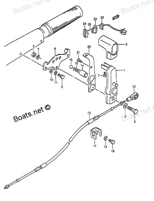
23230-95500 CLUTCH CABLE ASSEMBLY Suzuki
DT55CRLJ, DT55CRLK, DT55CRLL, DT55HTCLJ, DT55HTCLK, DT55HTCLL, DT55TCLJ, DT55TCLK, DT55TCLL, DT55TCLM, DT55TCLN, DT55TCLP, DT55TCLR, DT55TCLS, DT55TCLT, DT55TCLV, DT75TCLJ, DT75TCLK, DT75TCLL, DT75TCLM, DT75TCLN, DT75TCLP, DT75TCLR, DT75TCLS, DT75TCL
CLUTCH

Price: query
Rating:
This part in 4 request:
Show.
This information for suppliers only!
#102469 23230-95500
2024-04-17
#102377 23230-95500
2024-03-07
#102369 23230-95500
2024-03-02
#71561 23230-95500
2020-04-19
Number on catalog scheme: 13
Compatible models:
DT55CRLJ
DT55CRLK
DT55CRLL
DT55HTCLJ
DT55HTCLK
DT55HTCLL
DT55TCLJ
DT55TCLK
DT55TCLL
DT55TCLM
DT55TCLN
DT55TCLP
DT55TCLR
DT55TCLS
DT55TCLT
DT55TCLV
DT75TCLJ
DT75TCLK
DT75TCLL
DT75TCLM
DT75TCLN
DT75TCLP
DT75TCLR
DT75TCLS
DT75TCLT
DT75TCLV
DT85TCLJ
DT85TCLK
DT85TCLL
DT85TCLM
DT85TCLN
DT85TCLP
DT85TCLR
DT85TCLS
DT85TCLT
DT85TCLV
DT85TCLW
DT85TCLX
DT85TCLY
Suzuki
Suzuki entire parts catalog list:
- CLUTCH LEVER DT55HTC » 23230-95500
- CLUTCH LEVER DT55HTC » 23230-95500
- CLUTCH LEVER DT55HTC » 23230-95500
- CLUTCH LEVER DT55HTC » 23230-95500
- CLUTCH LEVER DT55HTC » 23230-95500
- CLUTCH LEVER DT55HTC » 23230-95500
- CLUTCH LEVER DT55HTC » 23230-95500
- CLUTCH LEVER DT55HTC » 23230-95500
- CLUTCH LEVER DT55HTC » 23230-95500
- CLUTCH LEVER DT55HTC » 23230-95500
- CLUTCH LEVER DT55HTC » 23230-95500
- CLUTCH LEVER DT55HTC » 23230-95500
- CLUTCH LEVER DT55HTC » 23230-95500
- CLUTCH LEVER DT55HTC » 23230-95500
- CLUTCH LEVER DT55HTC » 23230-95500
- CLUTCH LEVER DT55HTC » 23230-95500
- OPTIONAL HANDLE » 23230-95500
- OPTIONAL HANDLE 93-95 » 23230-95500
- OPTIONAL HANDLE » 23230-95500
- OPTIONAL HANDLE 93-95 » 23230-95500
- OPTIONAL HANDLE » 23230-95500
- OPTIONAL HANDLE 93-95 » 23230-95500
- OPTIONAL HANDLE 93-95 » 23230-95500
- OPTIONAL HANDLE » 23230-95500
- OPTIONAL HANDLE » 23230-95500
- OPTIONAL HANDLE 93-95 » 23230-95500
- OPTIONAL HANDLE » 23230-95500
- OPTIONAL HANDLE 93-95 » 23230-95500
- OPTIONAL HANDLE » 23230-95500
- OPTIONAL HANDLE 93-95 » 23230-95500
- OPTIONAL HANDLE » 23230-95500
- OPTIONAL HANDLE 93-95 » 23230-95500
- OPTIONAL HANDLE 93-95 » 23230-95500
- OPTIONAL HANDLE » 23230-95500
- OPTIONAL HANDLE » 23230-95500
- OPTIONAL HANDLE 93-95 » 23230-95500
- OPTIONAL HANDLE » 23230-95500
- OPTIONAL HANDLE 93-95 » 23230-95500
- OPTIONAL HANDLE 93-95 » 23230-95500
- OPTIONAL HANDLE » 23230-95500
- OPTIONAL HANDLE » 23230-95500
- OPTIONAL HANDLE 93-95 » 23230-95500
- OPTIONAL HANDLE » 23230-95500
- OPTIONAL HANDLE 93-95 » 23230-95500
- OPTIONAL HANDLE » 23230-95500
- OPTIONAL HANDLE 93-95 » 23230-95500
- OPTIONAL HANDLE 93-95 » 23230-95500
- OPTIONAL HANDLE » 23230-95500
- OPTIONAL HANDLE » 23230-95500
- OPTIONAL HANDLE 93-95 » 23230-95500
- OPTIONAL HANDLE 93-95 » 23230-95500
- OPTIONAL HANDLE » 23230-95500
- OPTIONAL HANDLE » 23230-95500
- OPTIONAL HANDLE 93-95 » 23230-95500
- OPTIONAL HANDLE 93-95 » 23230-95500
- OPTIONAL HANDLE » 23230-95500
- OPTIONAL HANDLE » 23230-95500
- OPTIONAL HANDLE 93-95 » 23230-95500
- OPTIONAL HANDLE » 23230-95500
- OPTIONAL HANDLE 93-95 » 23230-95500
- OPTIONAL HANDLE 93-95 » 23230-95500
- OPTIONAL HANDLE » 23230-95500
Information:
Personal injury can result from hydraulic oil pressure and hot oil.Hydraulic oil pressure can remain in the hydraulic system after the engine has been stopped. Serious injury can be caused if this pressure is not released before any service is done on the hydraulic system.Make sure all of the work tools have been lowered to the ground, and the oil is cool before removing any components or lines. Remove the oil filler cap only when the engine is stopped, and the filler cap is cool enough to touch with your bare hand.
Escaping fluid under pressure, even a pinhole size leak, can penetrate body tissue, causing serious injury, and possible death. If fluid is injected into your skin, it must be treated immediately by a doctor familiar with this type of injury.Always use a board or cardboard when checking for a leak.
Care must be taken to ensure that fluids are contained during performance of inspection, maintenance, testing, adjusting, and repair of the product. Be prepared to collect the fluid with suitable containers before opening any compartment or disassembling any component containing fluids.Refer to Special Publication, NENG2500, "Dealer Service Tool Catalog" for tools and supplies suitable to collect and contain fluids on Cat products.Dispose of all fluids according to local regulations and mandates.
Hydraulic System
Hydraulic oil pressure can remain in the hydraulic system on this machine after the engine and pump have been stopped. Serious injury can result if this pressure is not released before any service is done on the hydraulic system. In order to prevent possible injury, release the hydraulic system pressure before working on any fitting, hose, or hydraulic component.Lower all work tools to the ground before service is started. If the hydraulic system must be serviced, tested, or adjusted with the work tool in the raised position, the work tool and lift cylinders must be supported properly.Always move the machine to a location away from the travel of other machines. Be sure that other personnel are not near the machine when the engine is running and tests or adjustments are being made.
Park the machine on a hard, smooth, level surface. The location should also be dry and free of debris.
Permit only one operator on the machine. All other personnel should be kept away from the machine.
If the machine is equipped with a ride control system, place the ride control system into "Service".mode. Refer to "Ride Control" in this Operation and Maintenance, "Operator Controls" section.
Illustration 1 g02727672
Position the bucket or the work tool just above the ground at a slight downward angle. This position will ensure that the head end of the lift cylinders is pressurized.
Engage the parking brake.
Turn the engine start switch to the OFF position.
When the engine has stopped, turn the engine start switch back to the ON position so the pilot oil can reach the main valve.
Move the implement lockout switch to the UNLOCKED position.
Move the lift control lever to the FLOAT position and the tilt control lever to the TILT BACK position at the same time. This action allows the bucket or the work tool to tilt back while the boom is lowered.The bottom of the bucket or the work tool should rest flat on the ground. The weight of the linkage should be supported by the ground. The pressure from the head end of the lift cylinders and from the ride control accumulator is now vented to the hydraulic tank.
When the bucket or the work tool has settled to the ground, move both control levers to the HOLD position. Cycle the control levers through all positions several times in order to purge any remaining pressure from the implement hydraulic system. This action will completely drain the pilot accumulator.
Turn the engine start switch to the OFF position.
Slowly loosen the hydraulic tank filler cap in order to release the pressure from the hydraulic tank.
After all of the pressure has been released, tighten the hydraulic tank filler cap. The hydraulic system pressure has now been released. Hydraulic lines and components can now be removed.Release Procedure (Steering System, Braking System, and Quick Coupler) (If Equipped)
Personal injury can result from hydraulic oil pressure and hot oil.Hydraulic oil pressure can remain in the hydraulic system after the engine has been stopped. Serious injury can be caused if this pressure is not released before any service is done on the hydraulic system.Make sure all of the work tools have been lowered to the ground, and the oil is cool before removing any components or lines. Remove the oil filler cap only when the engine is stopped, and the filler cap is cool enough to touch with your bare hand.
Park the machine on a hard, smooth, level surface. The location should also be dry and free of debris.
Park the machine on a hard, smooth, level surface. The location should also be dry and free of debris.
Lower the bucket to the ground and stop the engine.
Engage the parking brake.
Turn the engine start switch to the OFF position.
Turn the steering wheel fully to the left and fully to the right several times to relieve the pressure in the steering system.
Depress the brake pedal repeatedly in order to release any pressure in the braking system. When no more resistance is felt and no pressure release is heard, the braking system, and Quick Coupler pressure is released.
Slowly loosen the hydraulic tank filler cap in order to release the pressure from the hydraulic tank.
After all of the pressure has been released, tighten the hydraulic tank filler cap. The hydraulic system pressure has now been released. Hydraulic lines and components can now be removed.
Parts clutch Suzuki:
21210-94703
21210-94703 CLUTCH SHAFT
DT55CLF, DT55CRLG, DT55CRLJ, DT55CRLK, DT55CRLL, DT55CRSG, DT55CRSH, DT55HTCLH, DT55HTCLJ, DT55HTCLK, DT55HTCLL, DT55TCLG, DT55TCLH, DT55TCLJ, DT55TCLK, DT55TCLL, DT55TCLM, DT55TCLN, DT55TCLP, DT55TCLR, DT55TCLS, DT55TCLT, DT55TCLV, DT55TCSG, DT55TCS
21213-94700
21213-94700 CLUTCH SHAFT SIDE ARM
DT55CLF, DT55CRLG, DT55CRLJ, DT55CRLK, DT55CRLL, DT55CRSG, DT55CRSH, DT55HTCLH, DT55HTCLJ, DT55HTCLK, DT55HTCLL, DT55TCLG, DT55TCLH, DT55TCLJ, DT55TCLK, DT55TCLL, DT55TCLM, DT55TCLN, DT55TCLP, DT55TCLR, DT55TCLS, DT55TCLT, DT55TCLV, DT55TCSG, DT55TCS
21311-94702
21311-94702 CLUTCH SHAFT HOLDER
DT55CLF, DT55CRLG, DT55CRLJ, DT55CRLK, DT55CRLL, DT55CRSG, DT55CRSH, DT55HTCLH, DT55HTCLJ, DT55HTCLK, DT55HTCLL, DT55TCLG, DT55TCLH, DT55TCLJ, DT55TCLK, DT55TCLL, DT55TCLM, DT55TCLN, DT55TCLP, DT55TCLR, DT55TCLS, DT55TCLT, DT55TCLV, DT55TCSG, DT55TCS
21211-95212
21211-95212 CLUTCH LEVER SHAFT
DT55CLF, DT55CRLG, DT55CRSG, DT55CRSH, DT55HTCLH, DT55TCLG, DT55TCLH, DT55TCSG, DT55TCSH, DT75TCLJ, DT75TCLK, DT75TCLL, DT75TCLM, DT75TCLN, DT75TCLP, DT75TCLR, DT75TCLS, DT75TCLT, DT75TCLV, DT85TCLJ, DT85TCLK, DT85TCLL, DT85TCLM, DT85TCLN, DT85TCLP,
23211-94702
23211-94702 CLUTCH CONTROL ARM
DT55CLF, DT55CRLG, DT55CRLJ, DT55CRLK, DT55CRLL, DT55CRSG, DT55CRSH, DT55HTCLH, DT55HTCLJ, DT55HTCLK, DT55HTCLL, DT55TCLG, DT55TCLH, DT55TCLJ, DT55TCLK, DT55TCLL, DT55TCLM, DT55TCLN, DT55TCLP, DT55TCLR, DT55TCLS, DT55TCLT, DT55TCLV, DT55TCSG, DT55TCS
21110-94702
21110-94702 CLUTCH LEVER
DT75TCLJ, DT75TCLK, DT75TCLL, DT75TCLM, DT75TCLN, DT75TCLP, DT75TCLR, DT75TCLS, DT75TCLT, DT75TCLV, DT85TCLJ, DT85TCLK, DT85TCLL, DT85TCLM, DT85TCLN, DT85TCLP, DT85TCLR, DT85TCLS, DT85TCLT, DT85TCLV, DT85TCLW, DT85TCLX, DT85TCLY
21150-95214-0ED
21150-95214-0ED CLUTCH LEVER BRACKET
DT75TCLJ, DT75TCLK, DT75TCLL, DT75TCLM, DT75TCLN, DT75TCLP, DT75TCLR, DT75TCLS, DT75TCLT, DT75TCLV, DT85TCLJ, DT85TCLK, DT85TCLL, DT85TCLM, DT85TCLN, DT85TCLP, DT85TCLR, DT85TCLS, DT85TCLT, DT85TCLV, DT85TCLW, DT85TCLX, DT85TCLY
23115-94720
23115-94720 CLUTCH LEVER LINK
DT75TCLJ, DT75TCLK, DT75TCLL, DT75TCLM, DT75TCLN, DT75TCLP, DT75TCLR, DT75TCLS, DT75TCLT, DT75TCLV, DT85TCLJ, DT85TCLK, DT85TCLL, DT85TCLM, DT85TCLN, DT85TCLP, DT85TCLR, DT85TCLS, DT85TCLT, DT85TCLV, DT85TCLW, DT85TCLX, DT85TCLY